
GOA display panel

a display panel and display technology, applied in the field of display technologies, can solve the problems of inability to meet the needs of consumers, lack of market competitiveness, and difficulty in implementing a narrow bezel, and achieve the effect of large rc loading

Active Publication Date: 2022-04-19
TCL CHINA STAR OPTOELECTRONICS TECH CO LTD
View PDF11 Cites 0 Cited by
  • Summary
  • Abstract
  • Description
  • Claims
  • Application Information

AI Technical Summary

Benefits of technology

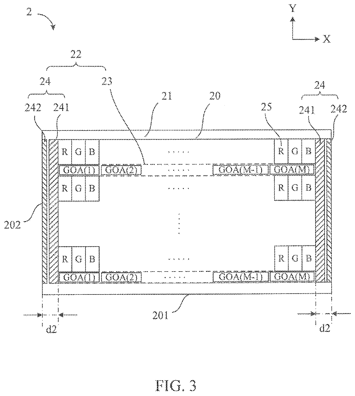
The present patent achieves a design for a super narrow bezel in a GOA display panel by arranging the cascaded GOA unit group within the display area. By setting the trace group of the GOA circuit in the bezel area to be separated from data lines of pixel units, the data lines do not overlap with the GOA bus in a longitudinal direction. This avoids problems of insufficient charging or uneven image display due to large RC loading.

Problems solved by technology

Therefore, how to implement a narrow bezel becomes a problem that must be solved.
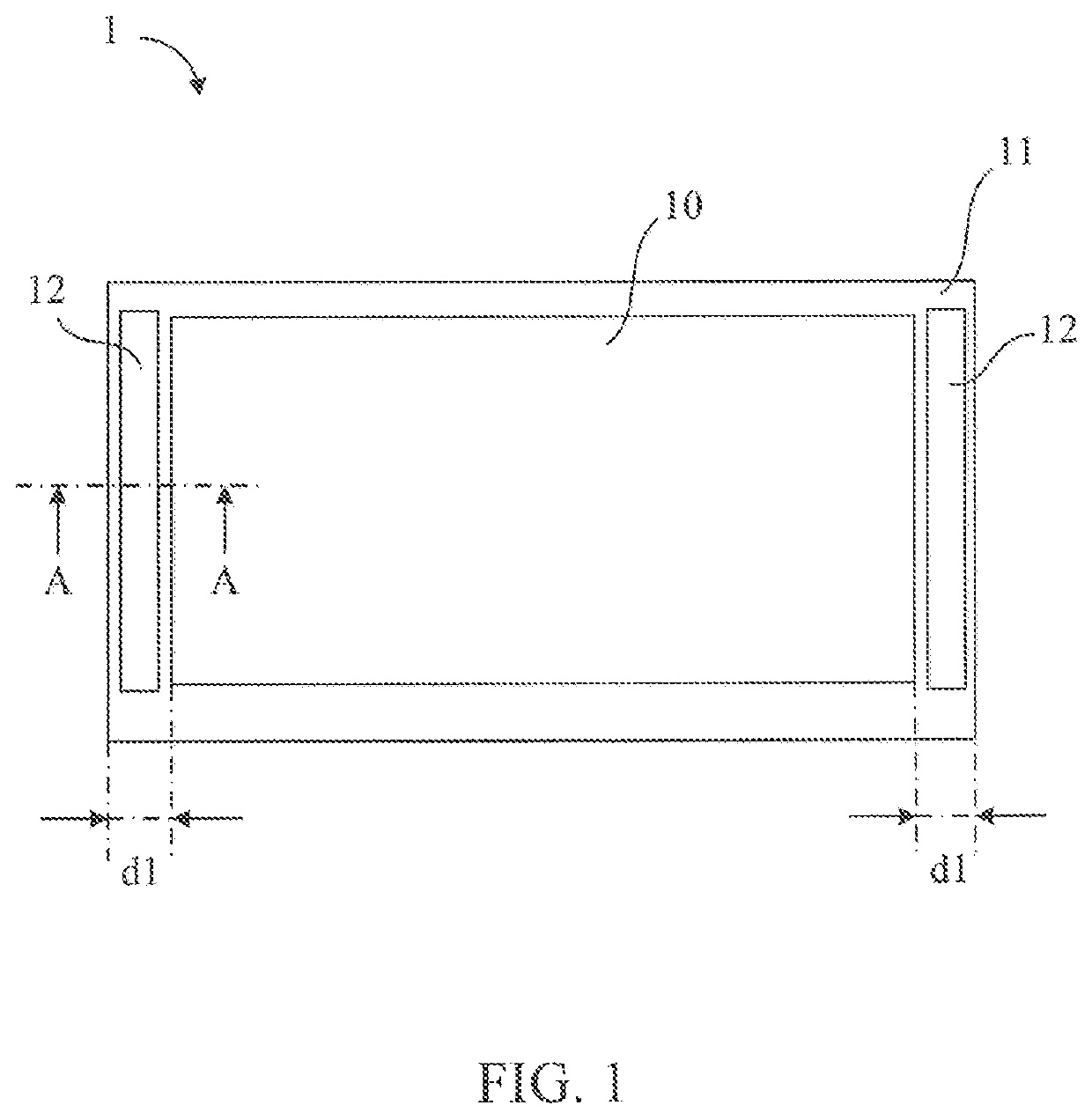
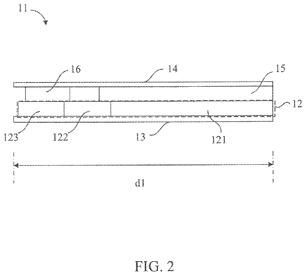
For example, in a case of existing products, the width d1 of the bezel area 11 is generally more than 5 mm, which cannot meet needs of consumers and lacks market competitiveness.

Method used


Image

  • GOA display panel
  • GOA display panel
  • GOA display panel

Examples


Embodiment Construction

[0030]The structure and the technical means adopted by the present disclosure to achieve the above and other objects can be best understood by referring to the following detailed description of the preferred embodiments and the accompanying drawings.

[0031]Please refer to FIG. 3, which is a schematic diagram of a GOA display panel 2 of a preferred embodiment of the present disclosure. The GOA display panel 2 is a display panel in which a gate driving circuit is formed on an array substrate instead of a driving chip fabricated from an external silicon chip. The display area 20 defines a display area 20 and a bezel area 21. The display area 20 is an active area of the display panel for displaying an image, and the bezel area 21 is surrounded by an outer periphery of the display area 20 and configured to be a layout space of circuits and related traces.

[0032]As shown in FIG. 3, the GOA display panel 2 includes a GOA circuit 22 and a plurality of pixel units 25. The plurality of pixel un...


PUM

PropertyMeasurementUnit
widthaaaaaaaaaa
width d1aaaaaaaaaa
widthaaaaaaaaaa

Abstract

A gate driver on array (GOA) display panel is provided, including a display area, a bezel area, a plurality of pixel units, and a GOA circuit. The plurality of pixel units are disposed in the display area in an array. The GOA circuit includes a GOA unit group and a trace group. The GOA unit group is disposed in the display area. The trace group is electrically connected to the GOA unit group and is disposed in the bezel area. The trace group includes a GOA bus and a common electrode line. A super narrow bezel design is achieved by arranging the cascaded GOA unit group of the GOA circuit within the display area.

Description

CROSS-REFERENCE TO RELATED APPLICATIONS[0001]This application is a U.S. National Phase of International PCT Application No. PCT / CN2019 / 107262 filed Sep. 23, 2019, which claims the benefit of Chinese Patent Application Serial No. 201910767691.0 filed Aug. 20, 2019, the contents of each application are incorporated herein by reference in their entirety.FIELD OF DISCLOSURE[0002]The present disclosure relates to the field of display technologies, and in particular to a GOA display panel.BACKGROUND[0003]A gate driver on array (GOA) technology is a technique of directly fabricating gate driver ICs on an array substrate instead of a driver chip fabricated from an external silicon chip. The GOA circuit can be directly disposed on a periphery of a panel to reduce production processes, thereby facilitating a design of a narrow bezel on a side of the GOA circuit of a display screen, and also reducing a production cost, so that it is widely used and researched.[0004]In response to consumer dema...

Claims


Application Information

Patent Timeline
Patent Type & Authority Patents(United States)
IPC IPC(8): G02F1/1343G09G3/20
CPCG09G3/20G09G2300/0408G09G2310/0294G09F9/00G09G2310/0264G09G2310/0286G09G2300/0426G09G2320/0223G09G2310/0267
Inventor ZHU, JING
Owner TCL CHINA STAR OPTOELECTRONICS TECH CO LTD
Learn More