Monitoring system, monitoring method and monitoring program for steam-using facility

a technology for monitoring systems and facilities, applied in the direction of program control, testing/monitoring control systems, instruments, etc., can solve the problem that the response speed may not be sufficiently high to detect abnormalities, and achieve the effect of unlikely loss of production opportunities

Active Publication Date: 2022-04-05
TLV CO LTD
View PDF19 Cites 0 Cited by
  • Summary
  • Abstract
  • Description
  • Claims
  • Application Information

AI Technical Summary

Benefits of technology

[0015]With this configuration, it is possible to find a sign of an abnormality relating to the steam supply valve, in addition to the steam trap. Accordingly, it is possible to infer what kind of abnormality is occurring in which part of the steam-using facility, with high accuracy, and therefore, appropriate maintenance can be performed with ease and production opportunities are unlikely to be lost.
[0017]With this configuration, the manager can immediately recognize the occurrence or the sign of the abnormality, and therefore, production opportunities are further unlikely to be lost.
[0019]With this configuration, the abnormality or the sign of the abnormality can be solved without manual maintenance being performed, and therefore, production opportunities are further unlikely to be lost.

Problems solved by technology

However, in the technology disclosed in Patent Document 1, the state of the steam control device needs to be detected, and the speed of response to a sign of an abnormality may not be sufficiently high.

Method used


Image

  • Monitoring system, monitoring method and monitoring program for steam-using facility
  • Monitoring system, monitoring method and monitoring program for steam-using facility
  • Monitoring system, monitoring method and monitoring program for steam-using facility

Examples


Embodiment Construction

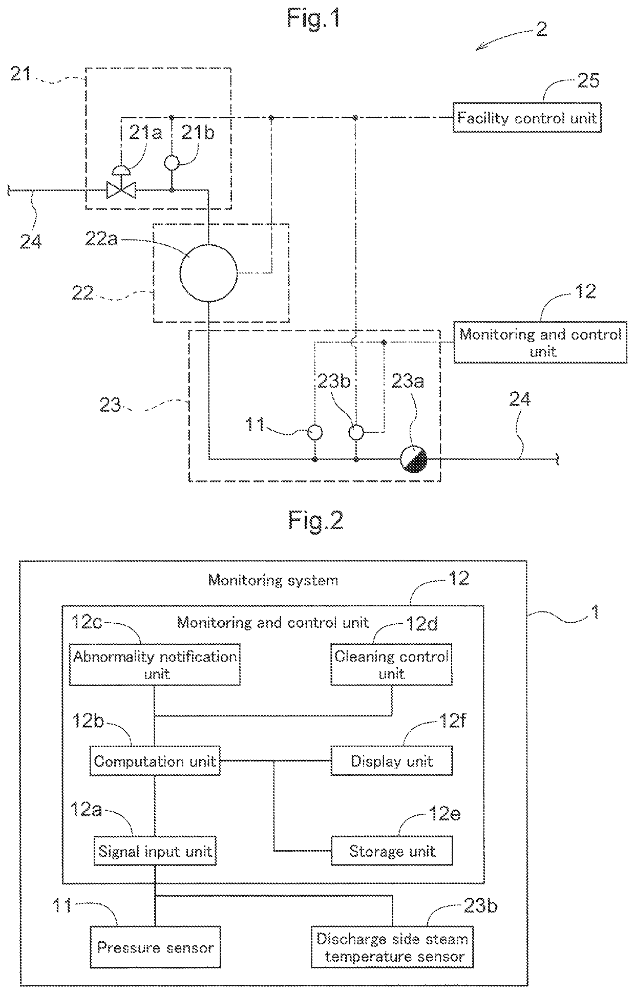
[0029]An embodiment of a monitoring system, a monitoring method, and a monitoring program according to the present invention will be described with reference to the drawings. The following describes, as an example, a method for monitoring a steam-using facility 2 by using a monitoring system 1 to which the monitoring system according to the present invention is applied. Note that the monitoring program according to the present invention is installed in the monitoring system 1.

[0030]In the claims, specification, drawings, and abstract of the present application, a “steam-using facility” means a facility that operates by consuming energy of steam, such as a device that is driven by kinetic energy taken out from steam or a device that heats a target object by consuming thermal energy of steam. Examples of steam-using facilities include a steam turbine, a hot-water generation unit, a press machine, an autoclave, a reactor, and a heater, but there is no limitation to these facilities.

[00...


PUM


Abstract

A monitoring system that monitors a steam-using facility includes a temperature sensor that is a trap temperature sensor configured to detect a temperature of a steam trap provided in a steam discharge unit and / or a steam temperature sensor configured to detect a temperature of steam flowing into the steam trap and a pressure sensor configured to detect a pressure of steam flowing into the steam trap. The monitoring system determines that there is an occurrence of an abnormality or a sign of the abnormality in the steam trap when (i) a temperature detection value obtained by the temperature sensor and / or statistical temperature data obtained by performing statistical processing on the temperature detection value deviates from a predetermined criterion thereof and (ii) a pressure detection value obtained by the pressure sensor and / or statistical pressure data obtained by performing statistical processing on the pressure detection value deviates from a predetermined criterion thereof.

Description

CROSS-REFERENCE TO RELATED APPLICATIONS[0001]This application is the United States national phase of International Application No. PCT / JP2019 / 041669 filed Oct. 24, 2019, and claims priority to Japanese Patent Application No. 2019-016298 filed Jan. 31, 2019, the disclosures of which are hereby incorporated by reference in their entirety.BACKGROUND OF THE INVENTIONField of the Invention[0002]The present invention relates to a monitoring system, a monitoring method, and a monitoring program for monitoring a steam-using facility.Description of Related Art[0003]If a steam-using device breaks down in a steam-using facility that is constituted by the steam-using device, the steam-using device needs to be repaired or replaced, and operation of the steam-using facility needs to be stopped for the repair or replacement, and accordingly, a repair cost or a replacement cost is incurred, and a profit that would otherwise be made by operating the steam-using facility will be lost, which may resul...

Claims


Application Information

Patent Timeline
Patent Type & Authority Patents(United States)
IPC IPC(8): G05B23/02F16T1/48G05B15/02F01D25/32F01D25/00
CPCG05B23/0259F01D25/00F01D25/32F16T1/48G05B15/02G05B23/024G05B19/0426G05B23/0283F01D5/005F01D17/145F01D21/12F01D25/002F05D2220/72F01D21/003F05D2270/00F05D2270/301F05D2270/303G05B23/02
Inventor NAKANISHI, KAZUKI
Owner TLV CO LTD
Why Eureka
Try Eureka