
Plastic scintillating fiber and method of manufacturing the same

a technology of scintillating fiber and plastic, which is applied in the direction of cladded optical fiber, x/gamma/cosmic radiation measurement, instruments, etc., can solve the problems of high cost, low accuracy of identifying the position of radiation passing through, and high rigidity of glass fibers such as this size, so as to reduce the dispersion and improve the accuracy of identifying the position

Active Publication Date: 2022-01-18
KURARAY CO LTD
View PDF31 Cites 1 Cited by
  • Summary
  • Abstract
  • Description
  • Claims
  • Application Information

AI Technical Summary

Benefits of technology

The invention provides a plastic fiber that can improve the accuracy of identifying the position where radiation passes through by reducing its dispersion.

Problems solved by technology

On the other hand, because organic fluorescent agents are sensitive to heat, application to glass fibers is difficult.
Glass fibers of such a size are highly rigid and difficult to be wound into bobbin and transported and stored, fragile and easily broken, and highly costly.
Thus, existing step-index plastic scintillating fibers have a problem that the accuracy of identifying a position which radiation passes through is low due to the modal dispersion.
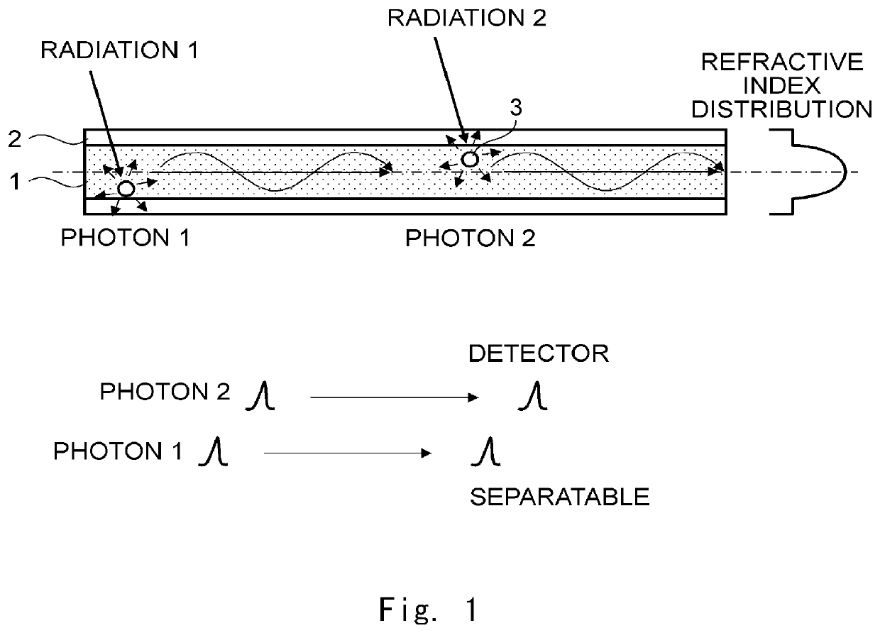
In such a case, the pulse width of signal pulses by photons 1 and 2 emitted by irradiation of the radial rays 1 and 2 spreads out due to the modal dispersion as shown in FIG. 4, and it is not possible to separate them from each other at the detector.
Consequently, the accuracy of identifying a position which radiation passes through is low.
In such a case also, the width of signals by photons 1 to 3 respectively emitted by irradiation of the radial rays 1 to 3 spreads out due to the modal dispersion as shown in FIG. 5, and it is not possible to separate them from one another at the detector.
Consequently, the accuracy of identifying a position which radiation passes through is low.

Method used


Image

  • Plastic scintillating fiber and method of manufacturing the same
  • Plastic scintillating fiber and method of manufacturing the same
  • Plastic scintillating fiber and method of manufacturing the same

Examples


examples

[0079]An example of the present invention is described hereinafter in more detail; however, the present invention is not limited to the following example. Note that the refractive index described in the example is a literature value at 20° C. or 25° C.

[0080]For plastic scintillating fibers according to an example and a comparative example, a resolving time (the degree of modal dispersion) of light signals after being guided through each plastic scintillating fiber was measured and compared. A method of measuring the resolving time is as follows.

[0081]A plastic scintillating fiber with a length of 20 m was prepared, its end face was polished using a 1500 grit sandpaper, and then was mirror-polished using an abrasive containing alumina of 0.3 μm.

[0082]A photomultiplier tube, which is a photo detector, was placed at one end of the plastic scintillating fiber, and a LED (wavelength=375 nm), which is a light source, was placed on a side face near the end face of the opposite side. A puls...

example

[0084]A benzyl methacrylate monomer (refractive index of homopolymer: 1.568) and a methyl methacrylate monomer (refractive index of homopolymer: 1.492) were fed by using a pair of micropumps under precise flow control.

[0085]In this example, each of the benzyl methacrylate monomer and the methyl methacrylate monomer contains a fluorescent agent p-terphenyl (PTP) 1 mass % and 2,5-bis-(5-t-butyl-benzoxazolyl) thiophene (BBOT) 0.02 mass %, and a polymerization initiator 1,1,3,3-tetramethylbutyl peroxy-2-ethylhexanoate (PO—O) 0.05 mass %, n-butyl-4,4-bis (t-butylperoxy) valerate (PH-V) 0.05 mass %, and a chain transfer agent n-octylmercaptan (n-OM) 0.25 mass % for molecular weight control.

[0086]The monomers were fed through a merging point and mixed by a static mixer, and further fed into the inlet. The monomers were then injected into a rotating glass ampoule while varying the feeding amount of the pair of micropumps, and thermally polymerized. As a result, a graded-index plastic rod wh...


PUM

PropertyMeasurementUnit
lengthaaaaaaaaaa
refractive indexaaaaaaaaaa

Abstract

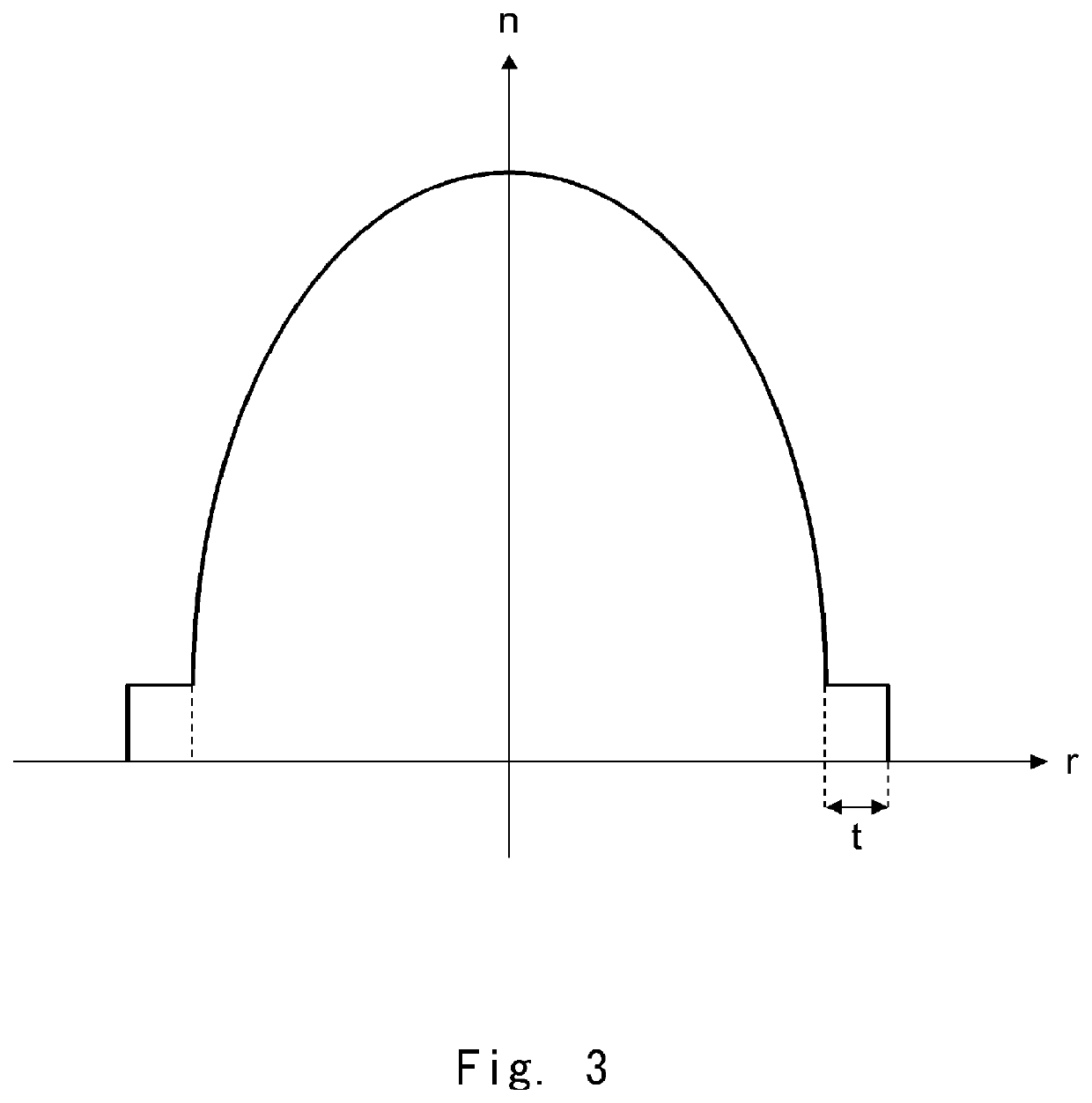
A plastic scintillating fiber capable of reducing modal dispersion and improving the accuracy of identifying a position which radiation passes through. A plastic scintillating fiber includes a core and a cladding that covers an outer periphery of the core and has a lower refractive index than the core. The core uniformly contains a radiation-emitting fluorescent agent and has a refractive index distribution where the refractive index of the core is highest at a center of a cross-section and becomes lower in a parabolic manner with distance from the center toward an outer periphery.

Description

TECHNICAL FIELD[0001]The present invention relates to a plastic scintillating fiber and a method of manufacturing the same and, particularly, to a plastic scintillating fiber and a method of manufacturing the same suitable for detection of high-dose radiation.BACKGROUND ART[0002]A plastic scintillating fiber (PSF) is a plastic fiber where a core, which is a scintillator, is covered on its outer periphery with a cladding having a lower refractive index than the core, and it is used mainly for detection of radiation. The core is typically made of a polymeric material where an organic fluorescent agent is added to a base material having an aromatic ring such as polystyrene or polyvinyl toluene, for example. The cladding is made of a low refractive index polymeric material such as polymethyl methacrylate or polymethyl methacrylate containing fluorine, for example.[0003]The principle of detection of radiation using a scintillating fiber is described hereinafter. When radiation (X-rays, h...

Claims


Application Information

Patent Timeline
Patent Type & Authority Patents(United States)
IPC IPC(8): G01T1/203G01T1/20G01T1/00B29D11/00G02B6/02B29C41/04G02B6/028
CPCG01T1/203B29C41/04B29D11/00682G01T1/00G01T1/20G02B6/02G02B6/028G01T1/201
Inventor SHINJI, OSAMUIWAKAWA, RYUICHI
Owner KURARAY CO LTD
Learn More