
Intelligent vehicles with advanced vehicle camera systems for underbody hazard and foreign object detection

a technology for underbody hazard and foreign objects, applied in the field of intelligent vehicles with advanced vehicle camera systems for underbody hazard and foreign object detection, to achieve the effects of ensuring the safety of the overall system, ensuring the safety of the underbody, and optimizing charging efficiency

Active Publication Date: 2022-01-18
GM GLOBAL TECH OPERATIONS LLC
View PDF17 Cites 3 Cited by
  • Summary
  • Abstract
  • Description
  • Claims
  • Application Information

AI Technical Summary

Benefits of technology

[0002]Current production motor vehicles, such as the modern-day automobile, are originally equipped with a powertrain that operates to propel the vehicle and power the vehicle's onboard electronics. In automotive applications, for example, the vehicle powertrain is generally typified by a prime mover that delivers driving power through an automatic or manually shifted power transmission to the vehicle's final drive system (e.g., differential, axle shafts, road wheels, etc.). Automobiles have historically been powered by a reciprocating-piston type internal combustion engine (ICE) assembly due to its ready availability and relatively inexpensive cost, light weight, and overall efficiency. Such engines include compression-ignited (CI) diesel engines, spark-ignited (SI) gasoline engines, two, four, and six-stroke architectures, and rotary engines, as some non-limiting examples. Hybrid electric and full electric (“electric-drive”) vehicles, on the other hand, utilize alternative power sources to propel the vehicle and, thus, minimize or eliminate reliance on a fossil-fuel based engine for tractive power.
[0004]High-voltage electrical systems govern the transfer of electricity between the traction motor(s) and a rechargeable traction battery pack (also referred to as “electric-vehicle battery”) that stores and supplies the requisite power for operating an electric-drive powertrain. A traction battery pack contains multiple stacks of battery cells that are packaged into individual battery modules and stored inside a battery pack housing. Some vehicular battery systems employ multiple independently operable, high-voltage battery packs to provide higher voltage delivery and greater system capacity through increased amp-hours. The vehicle's electric system may employ a front-end DC-to-DC power converter that is electrically connected to the vehicle's traction battery pack(s) in order to increase the voltage supply to a high-voltage main direct current (DC) bus and an electronic power inverter module (PIM). Operation and control of a multi-phase electric motor, such as permanent magnet synchronous traction motors, may be accomplished by employing the PIM to transform DC electric power to alternating current (AC) power using pulse-width modulated control signals output from a Battery Pack Control Module (BPCM).
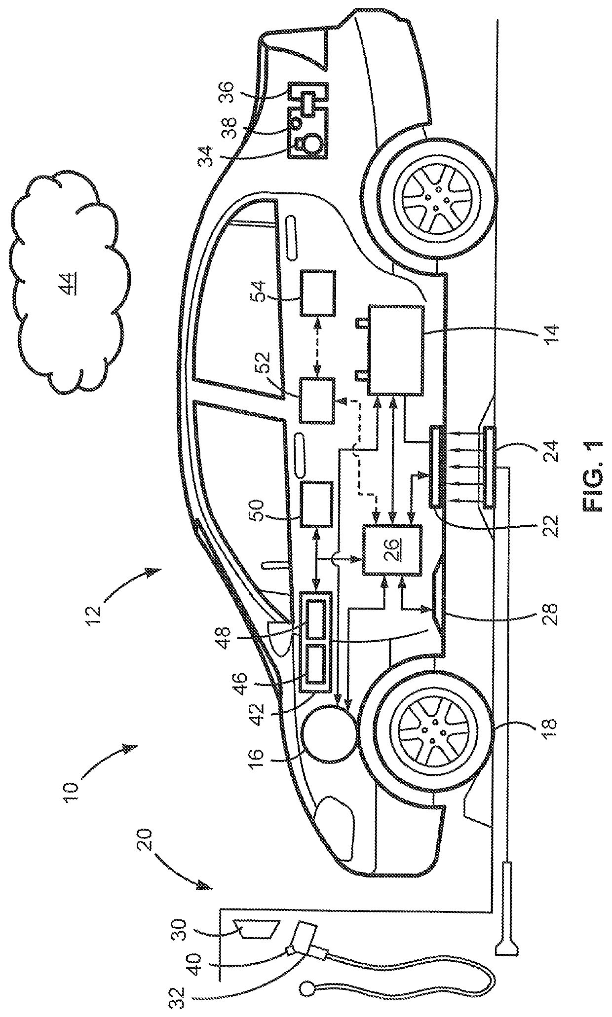
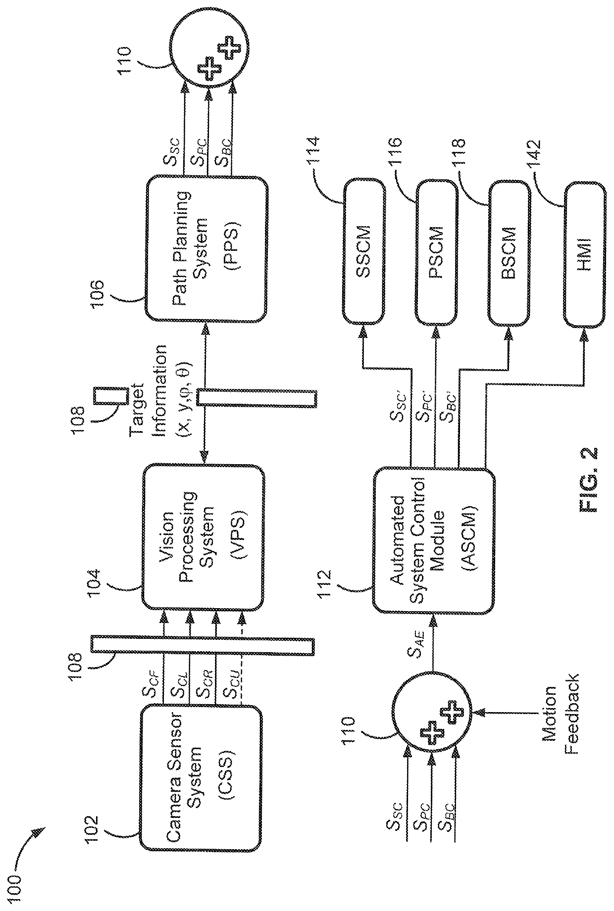
[0007]Attendant benefits for at least some of the disclosed concepts include novel vehicle system architectures that enable accurate and efficient underbody hazard and foreign object detection. Advanced vision-based APA systems are able to monitor for, identify, and ascertain precise location, shape, and size data of underbody foreign objects and hazards, and automate ameliorative measures to protect the vehicle and object. For wireless charging applications, disclosed features help to optimize charging efficiency while maintaining high levels of overall system robustness. Disclosed advanced driver assistance systems eliminate the need for dedicated sensors, video processing modules, and hardware accelerators for accurate underbody detection and protection during automated driving operations.

Problems solved by technology

It is axiomatic that large-scale vehicle electrification in turn necessitates a concomitant buildout of readily accessible charging infrastructure to support daily vehicle use in both urban and rural scenarios, for both short-distance and long-distance vehicle range.

Method used


Image

  • Intelligent vehicles with advanced vehicle camera systems for underbody hazard and foreign object detection
  • Intelligent vehicles with advanced vehicle camera systems for underbody hazard and foreign object detection
  • Intelligent vehicles with advanced vehicle camera systems for underbody hazard and foreign object detection

Examples


Embodiment Construction

[0021]This disclosure is susceptible of embodiment in many different forms. Representative embodiments of the present disclosure are shown in the drawings and will herein be described in detail with the understanding that these embodiments are provided as an exemplification of the disclosed principles, not limitations of the broad aspects of the disclosure. To that extent, elements and limitations that are described, for example, in the Abstract, Introduction, Summary, and Detailed Description sections, but not explicitly set forth in the claims, should not be incorporated into the claims, singly or collectively, by implication, inference or otherwise.

[0022]For purposes of the present detailed description, unless specifically disclaimed: the singular includes the plural and vice versa; the words “and” and “or” shall be both conjunctive and disjunctive; the words “any” and “all” shall both mean “any and all”; and the words “including,”“containing,”“comprising,”“having,” and the like,...


PUM


Abstract

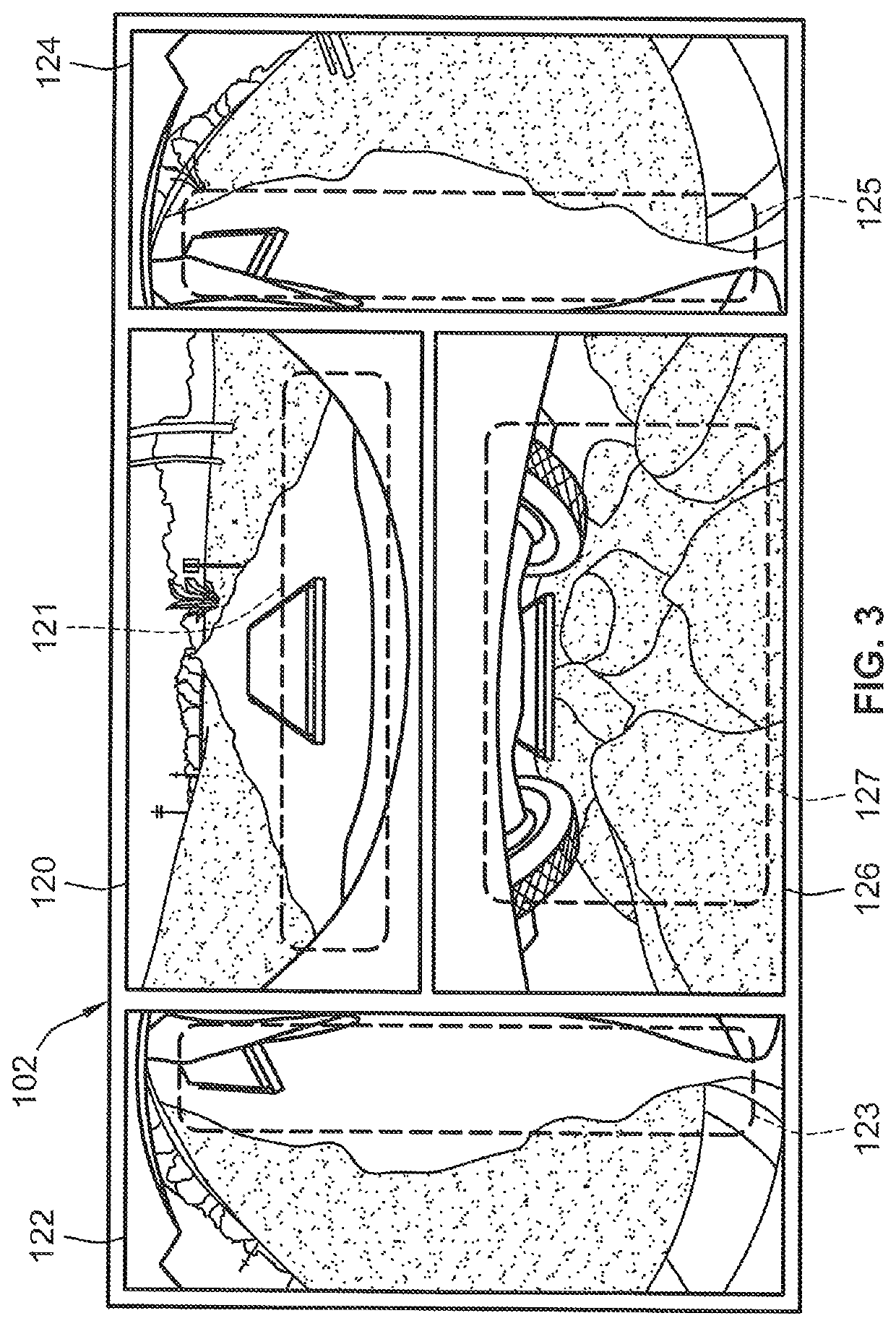
A method for operating an advanced driver assistance (ADAS) system of a motor vehicle includes a vehicle controller receiving, from side and end cameras mounted to the vehicle, camera signals indicative of real-time images of outboard-facing side and end views of the vehicle. The controller determines a region of interest (ROI) inset within each end / side view within which is expected foreign objects and / or hazards. These ROIs are analyzed to detect if a foreign object / hazard is present in the vehicle's end and / or side views. Responsive to detecting the foreign object / hazard, movement of the foreign object / hazard is tracked to determine if the foreign object / hazard moves towards or away from the vehicle's underbody region. If the foreign object / hazard moves to the underbody region, control signals are transmitted to the vehicle's propulsion and / or steering system to automate preventative action that prevents collision of the vehicle with and / or removes the foreign object / hazard from the underbody.

Description

INTRODUCTION[0001]The present disclosure relates generally to automated control systems of motor vehicles. More specifically, aspects of this disclosure relate to electric-drive vehicles with control logic for automating underbody hazard detection and foreign object protection.[0002]Current production motor vehicles, such as the modern-day automobile, are originally equipped with a powertrain that operates to propel the vehicle and power the vehicle's onboard electronics. In automotive applications, for example, the vehicle powertrain is generally typified by a prime mover that delivers driving power through an automatic or manually shifted power transmission to the vehicle's final drive system (e.g., differential, axle shafts, road wheels, etc.). Automobiles have historically been powered by a reciprocating-piston type internal combustion engine (ICE) assembly due to its ready availability and relatively inexpensive cost, light weight, and overall efficiency. Such engines include c...

Claims


Application Information

Patent Timeline
Patent Type & Authority Patents(United States)
IPC IPC(8): H04N5/247G07C5/08B60L53/124B60W30/09B60W10/20B60W10/18B60W40/02B60W10/04G08G1/16H04N7/18H02J50/60B60L53/126B60L53/36B60L50/60G05D1/02G06K9/00G06V10/25G06V10/44G06V10/764
CPCB60L53/124B60L50/66B60L53/126B60L53/36G07C5/08G07C5/0825G07C5/0891G05D1/0246G06K9/00791B60W30/08B60W30/09B60W50/14B60W10/04B60W10/18B60W10/20H04N7/181B60W2050/143B60W2420/42B60W2710/18B60W2710/20H04N23/90H02J50/60B60L53/37B60L53/38Y02T10/70Y02T10/7072Y02T90/12Y02T90/14H02J50/10H02J2310/48B60W2422/00B60W2556/10B60W2554/4044B60W30/095G06V20/56G06V10/25G06V10/44G08G1/165G08G1/168G06V10/764H04N23/61H04N23/635H04N23/80G01S17/931G01S2013/932G01S2013/9318G01S2013/9319G01S2013/93185
Inventor PRASAD, RASHMINAMUDURI, CHANDRA S.ALURU, SAI VISHNUSTANEK, CHRISTOPHER A.
Owner GM GLOBAL TECH OPERATIONS LLC
Learn More