
Phosphole compound

a compound and phosphorescence technology, applied in the field of phosphorescence compound, can solve the problems of limited object observation by the state-of-the-art fluorescence microscopy technique, difficult observation of repeated super-resolution microscopy, and decomposition of conventionally known fluorescent organic compounds, etc., to achieve enhanced fluorescence quantum yield and high fluorescence quantum yield

Active Publication Date: 2021-11-16
NAGOYA UNIVERSITY
View PDF7 Cites 0 Cited by
  • Summary
  • Abstract
  • Description
  • Claims
  • Application Information

AI Technical Summary

Benefits of technology

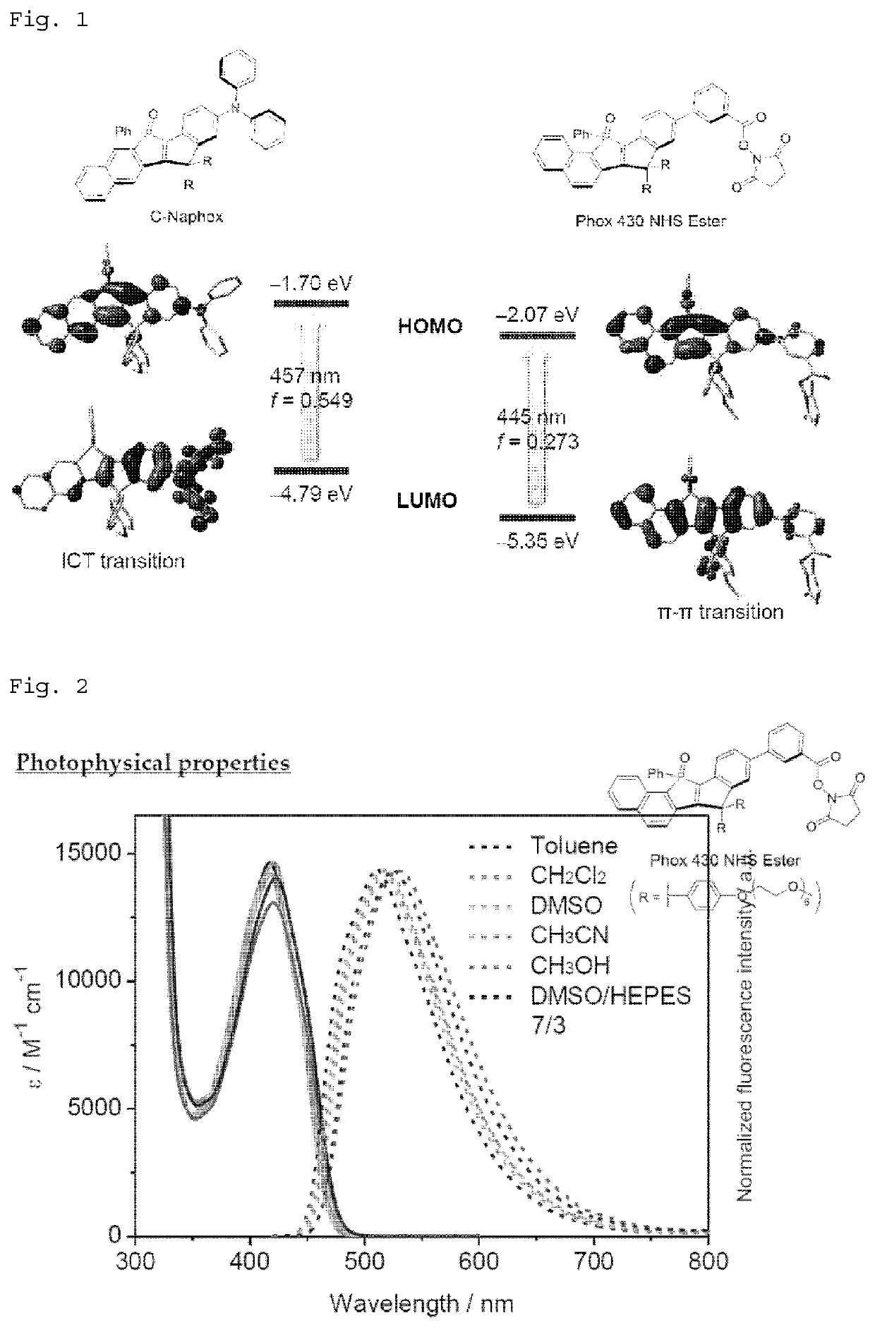
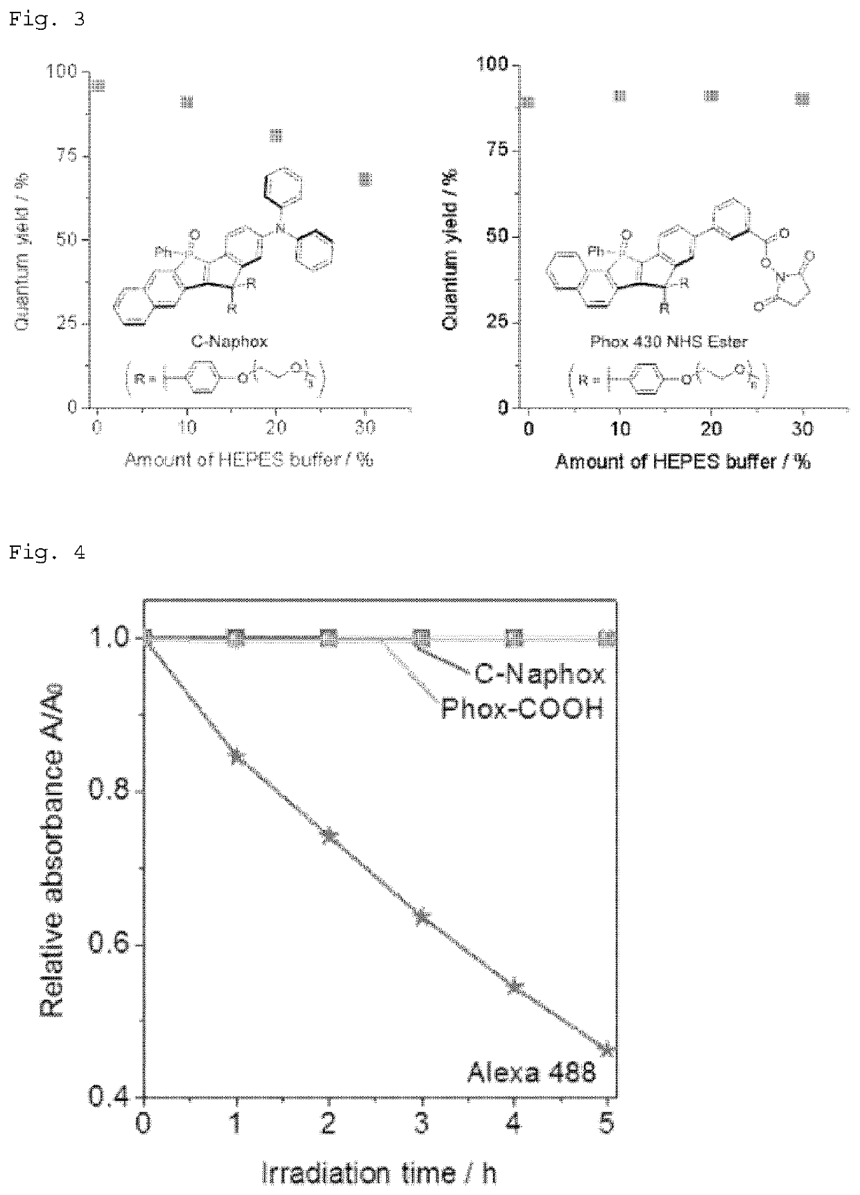
[0015]The phosphole compound of the present invention has an absorption peak in the visible light wavelength range (in particular, about 400 to 500 nm) irrespective of solvent polarity, and has a high fluorescence quantum yield. Furthermore, the phosphole compound of the present invention can have enhanced fluorescence quantum yield even in environments containing large amounts of water, and is widely applicable to fluorescence bioimaging of cells, tissues, living organisms, etc.
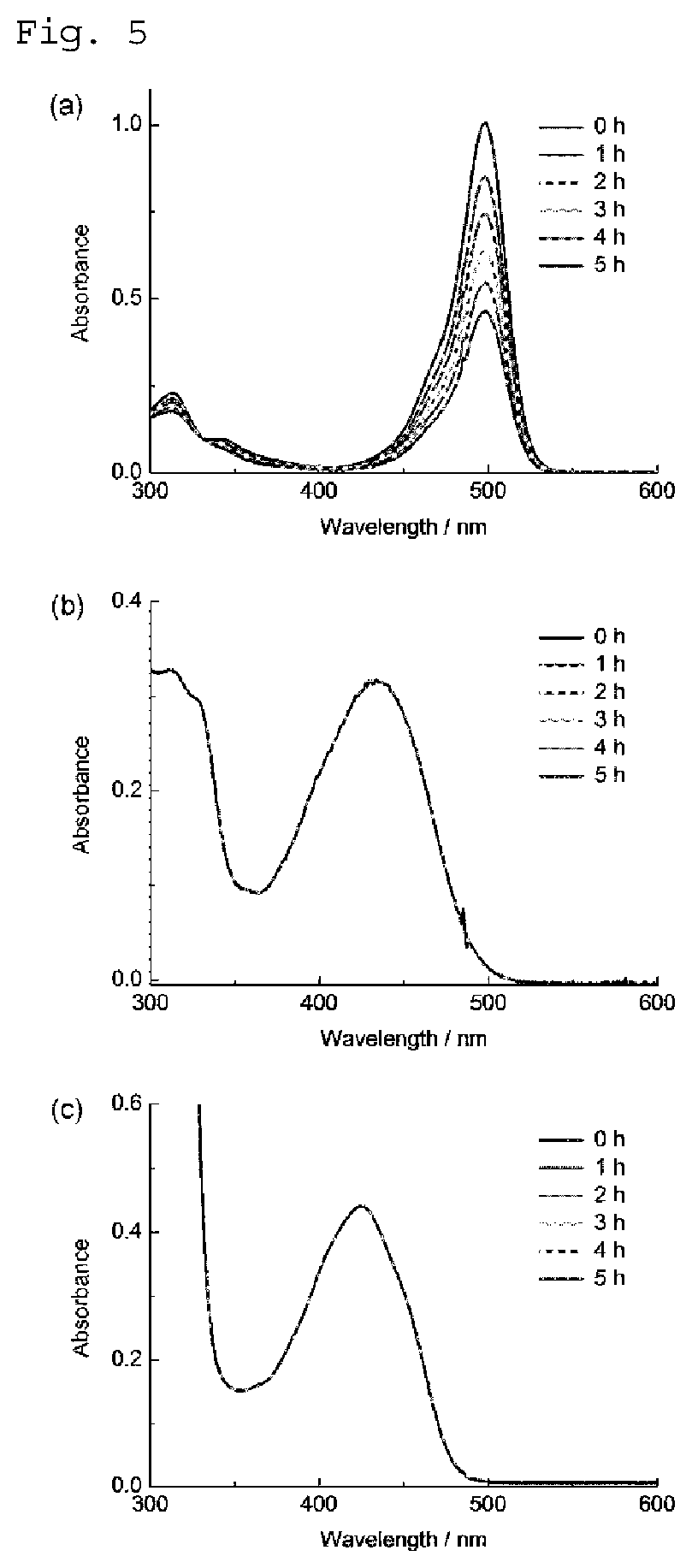
[0016]Therefore, the phosphole compound of the present invention is a fluorescent dye suitable for repeated super-resolution microscopy observation, such as stimulated emission depletion (STED) imaging.
[0017]Furthermore, the phosphole compound of the present invention wherein the reactive group represented by Z is an amine reactive group or a thiol reactive group can function as a protein labeling agent that labels proteins.

Problems solved by technology

However, with continued irradiation with light, many of the conventionally known fluorescent organic compounds gradually decompose and suffer from photobleaching.
However, repeated super-resolution microscopy observation, such as stimulated emission depletion (STED) imaging, is difficult even with use of such dyes.
Therefore, the object to be observed by the state-of-the-art fluorescence microscopy technique is limited at present, and improvement in light resistance of fluorescent dyes has been desired.

Method used


Image

  • Phosphole compound
  • Phosphole compound
  • Phosphole compound

Examples


synthesis example 1

nd 1 (1-bromo-2-(4-trimethylsilylphenylethynyl)naphthalene)

[0171]

(wherein Tf represents trifluoromethane sulfonyl, TMS represents trimethylsilyl, Pd(PPh3)4 represents tetrakis(triphenylphosphine) palladium (0), and Et3N represents triethylamine; the same applies below). A solution of 1-bromonaphthalen-2-yl triflate (99.44 g, 280 mmol) and 4-trimethylsilylphenylacetylene (48.80 g, 280 mmol) in triethylamine (Et3N; 500 mL) was degassed by bubbling dry nitrogen gas for 20 minutes. After tetrakis(triphenylphosphine)palladium (0) (Pd(PPh3)4; 3.24 g, 2.80 mmol) and CuI (0.533 g, 2.80 mmol) were added, the mixture was stirred at 60° C. for 20 hours. After the mixture was cooled to room temperature, the resulting inorganic salt was removed by filtration, and the filtrate was washed with toluene (200 mL). After all volatile substances were distilled off under reduced pressure, the residue was separated by silica gel column chromatography (hexane, Rf=0.24), and the obtained crude product was ...

synthesis example 2

nd 2 (3-bromo-1-phenyl-2-(4-trimethylsilylphenyl)naphtho[1,2-b]phosphole-P-oxide)

[0173]

(In the formula, tBuLi represents tert-butyl lithium, PhP(NEt2)Cl represents chloro(phenyl)(diethylamino)phosphine, PBr3 represents phosphorus tribromide, and Ph represents phenyl; the same applies below.)

[0174]A 1.60M pentane solution (100.5 mL) of tert-butyl lithium (tBuLi) (160.8 mmol) was added dropwise to a solution of compound 1 of Synthesis Example 1 (30.50 g, 80.4 mmol) in anhydrous tetrahydrofuran (THF; 400 mL) at −78° C. After the mixture was stirred at −78° C. for 1 hour, the resulting suspension was slowly warmed up to −40° C. over 2 hours. After the mixture was cooled to −78° C., chloro(phenyl) (diethylamino)phosphine (PhP(NEt2)Cl; 15.5 mL, 80.5 enol) was added thereto over 0.5 hours. The obtained mixture was slowly warmed up to 0° C. over 0.5 hours. After the mixture was cooled again to −78° C., phosphorus tribromide (PBr3; 7.64 mL, 80.4 enol) was added over 0.5 hours. The obtained m...

synthesis example 3

nd 3

[0176]

(wherein Me represents methyl; the same applies below).

[0177]HSiCl3 (8.07 mL, 80.0 mmol) was added at once to a suspension of compound 2 obtained in Synthesis Example 2 (10.07 g, 20.0 mmol) in anhydrous toluene (30 mL). After the resulting mixture was stirred at 50° C. for 1 hour, all volatiles were distilled off under reduced pressure. Toluene (20 mL) was then added to the resulting mixture, and the obtained suspension was filtered through Celite (registered trademark). The filtrate was washed with toluene (10 mL). After the filtrate was concentrated under reduced pressure, the obtained white solid was suspended in anhydrous diethyl ether (Et2O; 100 mL). A 1.60M pentane solution (25.0 mL) of tert-butyl lithium (tBuLi) (40.0 mmol) was added to this suspension at −78° C. over 30 minutes. After the resulting mixture was stirred at the same temperature for 2 hours, 4,4′-dimethoxybenzophenone (4.85 g, 20.0 mmol) was added, and the obtained mixture was slowly warmed to room tem...


PUM

PropertyMeasurementUnit
wavelengthaaaaaaaaaa

Abstract

A phosphole compound represented by the formula(wherein Ar1 and Ar2 are the same or different, and represent an optionally substituted aromatic hydrocarbon ring or an optionally substituted heteroaromatic ring; Ar3 represents a divalent π-conjugated unit; R1 represents an optionally substituted alkyl group, an optionally substituted cycloalkyl group, an optionally substituted aryl group, or an optionally substituted heteroaryl group; R2 and R3 are the same or different, and represent a hydrogen atom, an optionally substituted alkyl group, an optionally substituted cycloalkyl group, an optionally substituted aryl group, or an optionally substituted heteroaryl group; and Z represents a reactive group) can provide a fluorescent dye capable of maintaining a high fluorescence quantum yield irrespective of solvent polarity, and providing an improved fluorescence quantum yield and light resistance even in environments containing large amounts of water.

Description

CROSS-REFERENCE TO RELATED APPLICATIONS[0001]This application is a U.S. National Stage application of PCT / JP2017 / 026732 filed 24 Jul. 2017, which claims priority to Japanese Application No. 2016-168880 filed 31 Aug. 2016, the entire disclosures of which are incorporated herein by reference.TECHNICAL FIELD[0002]The present invention relates to a phosphole compound.BACKGROUND ART[0003]Fluorescent organic compounds that have high fluorescence quantum yields are important as luminescent materials for organic EL elements or as fluorescent dyes for in vivo fluorescence imaging. There have been numerous reports on both basic research and applied research of fluorescent organic compounds.[0004]However, with continued irradiation with light, many of the conventionally known fluorescent organic compounds gradually decompose and suffer from photobleaching. For example, as fluorescent probes, Alexa Fluor dye, ATTO dye, etc. are well known as a group of dyes having improved light resistance. How...

Claims


Application Information

Patent Timeline
Patent Type & Authority Patents(United States)
IPC IPC(8): C09B57/00C09K11/06G01N21/64G01N33/58C07F9/6568A61K49/00
CPCC09B57/00A61K49/00C07F9/6568C09K11/06G01N21/64G01N21/6428G01N33/582G01N2021/6439
Inventor YAMAGUCHI, SHIGEHIRONAKA, AIKOTAKI, MASAYASUWANG, CHENGUANG
Owner NAGOYA UNIVERSITY
Learn More