
Encoder and signal processing circuit

a signal processing circuit and encoder technology, applied in the direction of optical conversion of sensor output, electrical analogue stores, instruments, etc., can solve the problems of reduced position detection accuracy due to differences in arithmetic operation timing, scale of signal processing circuit increases, etc., and achieves simple configuration and high accuracy of position detection.

Active Publication Date: 2021-10-05
MITUTOYO CORP
View PDF18 Cites 0 Cited by
  • Summary
  • Abstract
  • Description
  • Claims
  • Application Information

AI Technical Summary

Benefits of technology

[0026]The present invention was conceived in light of the circumstances above, and the present invention achieves highly accurate position detection in an optical encoder, independent of variation in power supply voltage, through a simple configuration.
[0032]According to the present invention, highly accurate position detection in an optical encoder can be achieved, independent of variation in power supply voltage, through a simple configuration.

Problems solved by technology

Although an effect of variation in the power supply voltage or the reference voltage can be inhibited by using two sampling circuits as described above, the sample and hold circuit uses an operational amplifier or the like having a comparatively large circuit scale, and therefore there is an issue that the scale of the signal processing circuit increases.
As noted above, even in a configuration corresponding to the four-phase signals, although the output voltage for each phase can be made constant, the reference voltage REF (to which the output voltage is compared during the arithmetic operation) varies, and therefore a reduction in position detection accuracy due to differences in arithmetic operation timing is unavoidable.

Method used


Image

  • Encoder and signal processing circuit
  • Encoder and signal processing circuit
  • Encoder and signal processing circuit

Examples


first embodiment

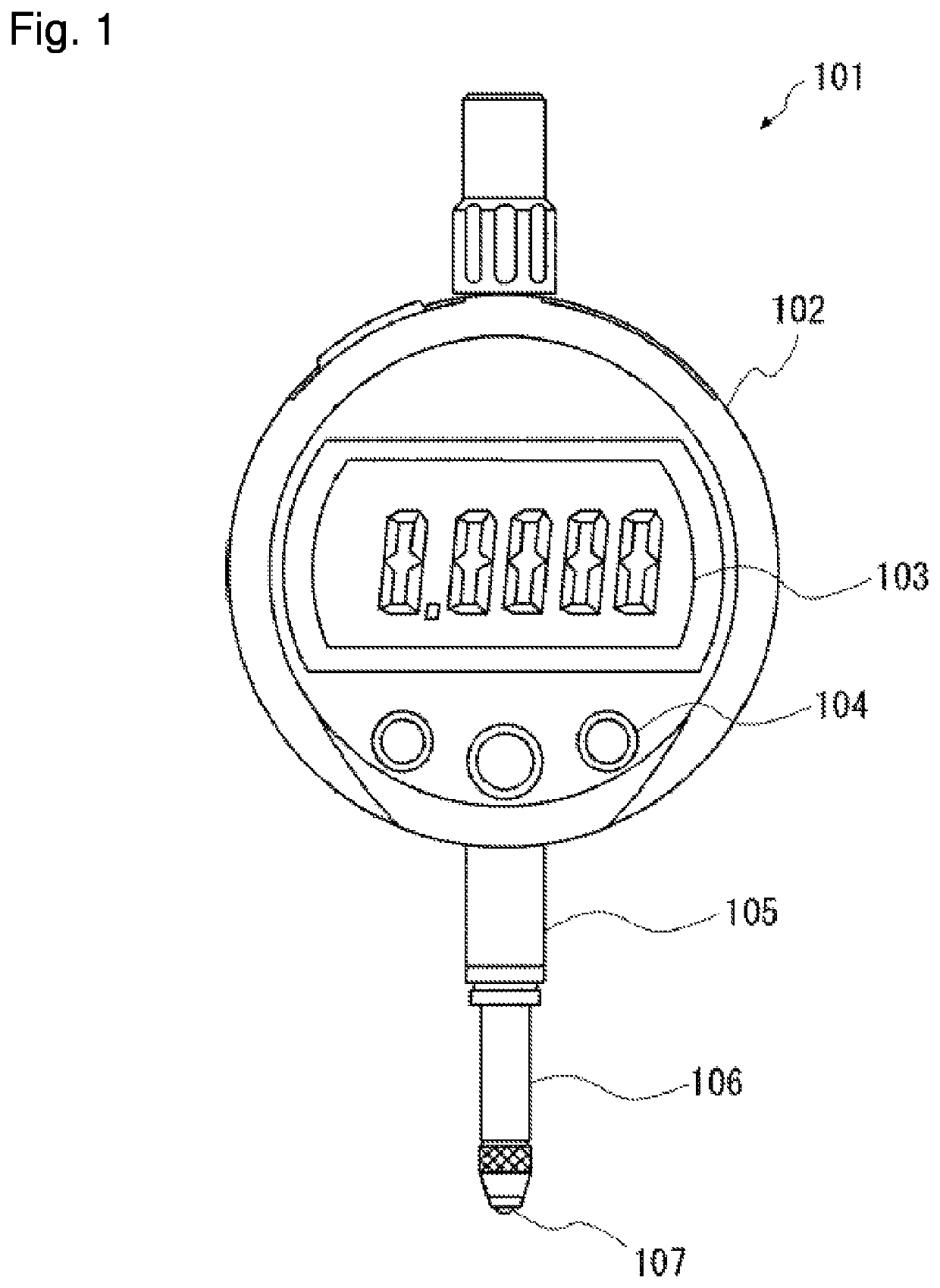
[0045]An optical encoder according to a first embodiment is described. FIG. 1 is a front view schematically illustrating a configuration of a dial gauge 101 that incorporates the optical encoder according to the first embodiment. The dial gauge 101 includes a main body 102, a display 103, an operation button 104, a stem 105, a spindle 106, a stylus head 107, and an output port 108.

[0046]The main body 102 has a substantially rounded pillar shape where the height in the vertical direction of the drawing plane of FIG. 1 is less than the width in the horizontal direction of the drawing plane of FIG. 1. The display 103 displaying a measured value, for example, is provided on one surface of the main body 102.

[0047]The stem 105 has a substantially cylindrical shape, and is provided so as to project from an exterior edge of the main body 102.

[0048]The spindle 106 is a substantially cylindrical member, is inserted through the stem 105, and is supported so as to be capable of sliding in a len...


PUM


Abstract

A reference voltage generator circuit generates a reference voltage corresponding to a power supply voltage. A current / voltage converter circuit converts a photocurrent output by a photoreceiver into voltage, and outputs a voltage obtained by adding the converted voltage and the reference voltage. A sample and hold circuit holds a voltage of a capacitor in response to a sample and hold signal, the capacitor having the voltage input at one end and the reference voltage input at another end. An amplifier circuit outputs an output signal where a voltage held by the sample and hold circuit is amplified with the reference voltage as a reference.

Description

CROSS-REFERENCE TO RELATED APPLICATIONS[0001]The present application claims priority under 35 U.S.C. § 119 of Japanese Application No. 2016-226888, filed on Nov. 22, 2016, the disclosure of which is expressly incorporated by reference herein in its entirety.BACKGROUND OF THE INVENTION1. Field of the Invention[0002]The present invention relates to an encoder and a signal processing circuit.2. Description of Related Art[0003]An encoder is installed in displacement measurement devices such as a dial gauge or indicator in order to measure an amount of displacement. A known example of such an encoder is an optical encoder that uses optical interference to measure the amount of displacement. Furthermore, encoders are broadly separated into incremental encoders, which measure a relative amount of displacement, and absolute encoders, which detect an absolute position. The specification of Japanese Patent No. 5,771,070, for example, suggests a configuration for an absolute-type optical encod...

Claims


Application Information

Patent Timeline
Patent Type & Authority Patents(United States)
IPC IPC(8): G01D5/34G01D5/347G01D5/244G11C27/02
CPCG01D5/34707G01D5/24428G01D5/34715G11C27/026G01D5/34746G01B11/02G01D5/26G01D5/38
Inventor KAWATOKO, OSAMUTAHARA, TOMOHIROKOBAYASHI, HIROKAZU
Owner MITUTOYO CORP
Learn More