Two-dimension precision transfer equipment, three-dimension precision transfer equipment, and coordinate measuring machine
a technology of precision transfer equipment and equipment, which is applied in the direction of mechanical measuring arrangements, instruments, manufacturing tools, etc., can solve the problems of mechanical connection of bellows that may become unmaintainable, laser path bent, and difficult coaxial arrangement of laser path, etc., to achieve high precision positioning, high precision movement, and high precision position detection
- Summary
- Abstract
- Description
- Claims
- Application Information
AI Technical Summary
Benefits of technology
Problems solved by technology
Method used
Image
Examples
first exemplary embodiment
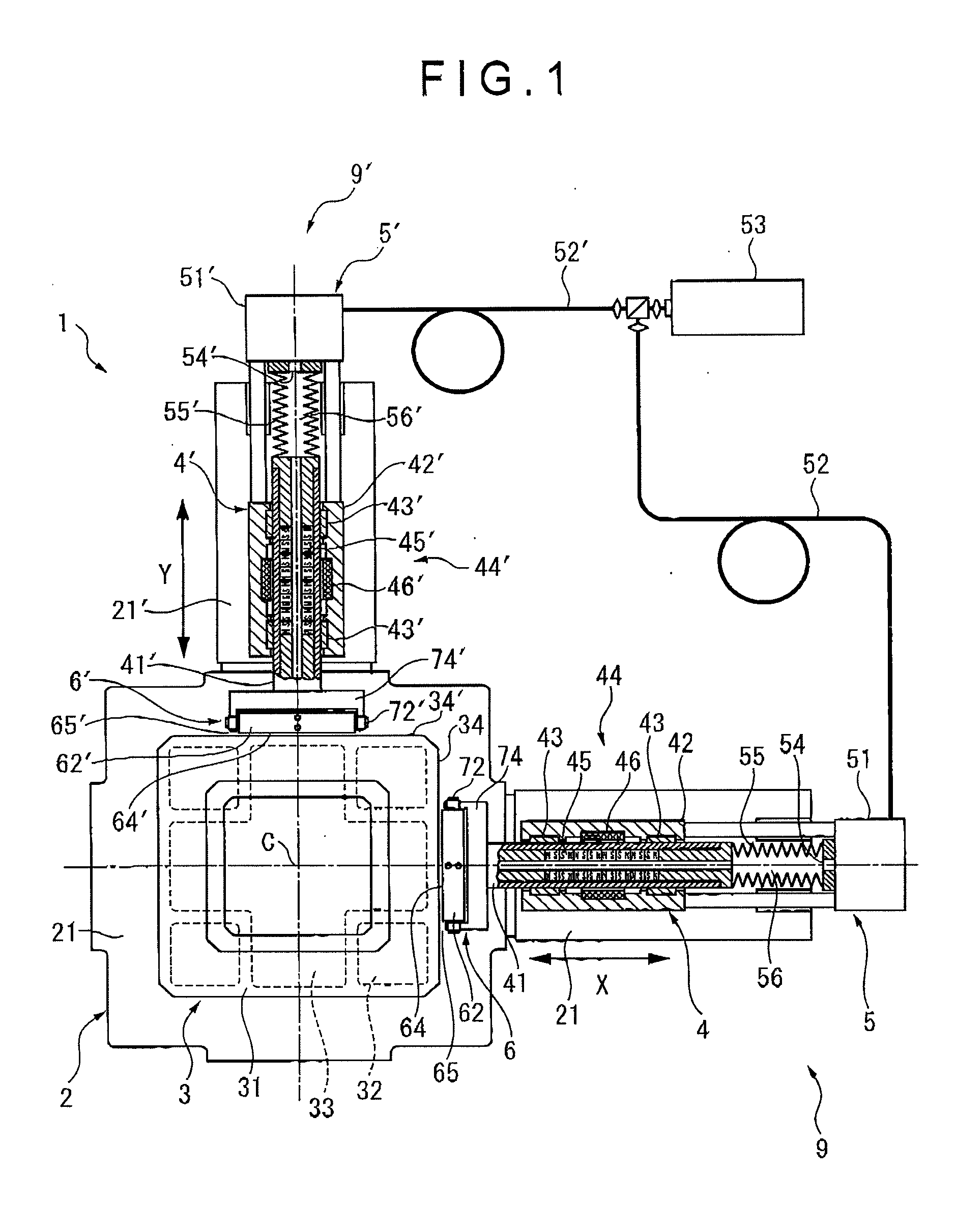
[0092]FIGS. 1 to 4 show a first exemplary embodiment of the invention.
[0093]In FIG. 1, two-dimension precision transfer equipment 1 according to the first exemplary embodiment includes: a base 2; and a table mechanism 3, a first drive mechanism 4, a second drive mechanism 4′, a first laser interferometer 5 (a first displacement detector) and a second laser interferometer 5′ (a second displacement detector) provided on the base 2.
[0094]As shown in FIG. 2 the base 2 is a block member fixed on a stable foundation. An upper surface 21 of the base 2 is formed horizontally.
[0095]A support base 22 that laterally projects is provided on a side of the base 2. The first and second drive mechanisms 4 and 4′ and the first and second laser interferometers 5 and 5′ are supported by the support base 22 so as to be positioned at the same height as the table 31 of the table mechanism 3.
[0096]The upper surface 21 of the base 2 is processed to have a sufficiently high flatness and smoothness so as to ...
second exemplary embodiment
[0150]FIG. 5 shows a second exemplary embodiment of the invention.
[0151]Two-dimension precision transfer equipment 1A according to the second exemplary embodiment includes the same basic components as those in the two-dimension precision transfer equipment 1 according to the first exemplary embodiment. The same components are given with the same reference numerals in which overlapping description of the components will be omitted. A difference between the two-dimension precision transfer equipment 1A and 1 will be described below.
[0152]As shown in FIG. 5, in the second exemplary embodiment, joint members 62A and 62A′ of first and second joints 6A and 6A′ are not provided with the through holes 68 and 68′ and the transparent plates 69 and 69′ of the first exemplary embodiment (see FIG. 4).
[0153]Instead, the joint members 62A and 62A′ are provided with mirrors 57 and 57′ in an area surrounded by the bellows 57 and 57′.
[0154]The mirrors 57 and 57′ are provided so as to be orthogonal to...
third exemplary embodiment
[0163]FIG. 6 shows a third exemplary embodiment of the invention.
[0164]Two-dimension precision transfer equipment 1B according to the second exemplary embodiment includes the same basic components as those in the two-dimension precision transfer equipment 1 according to the first exemplary embodiment. The same components are given with the same reference numerals in which overlapping description of the components will be omitted. A difference between the two-dimension precision transfer equipment 1B and 1 will be described below.
[0165]In FIG. 6, in the third exemplary embodiment, joint members 62B and 62B′ of first and second joints 6B and 6B′ are not provided with the through holes 68 and 68′ and the transparent plates 69 and 69′ of the first exemplary embodiment (see FIG. 4). Moreover, the turn shaft 72 and the support member 74 as described in the first exemplary embodiment are not provided in order to connect the joint members 62B and 62B′ with first and second rods 41B and 41B′...
PUM
 Abstract
Description
Claims
Application Information
 - R&D
- Intellectual Property
- Life Sciences
- Materials
- Tech Scout
- Unparalleled Data Quality
- Higher Quality Content
- 60% Fewer Hallucinations
Browse by: Latest US Patents, China's latest patents, Technical Efficacy Thesaurus, Application Domain, Technology Topic, Popular Technical Reports.
© 2025 PatSnap. All rights reserved.Legal|Privacy policy|Modern Slavery Act Transparency Statement|Sitemap|About US| Contact US: help@patsnap.com


