
Method for controlling and/or regulating the operation of an internal combustion engine

a technology of internal combustion engine and control method, which is applied in the direction of combustion engine, electric control, machines/engines, etc., can solve the problems of unoptimized methods, uncontrollable internal combustion engine operation, and possible engine damage, so as to reduce the slow response of internal combustion engine and/or avoid the effect of sluggish respons

Active Publication Date: 2021-09-14
VOLKSWAGEN AG
View PDF15 Cites 0 Cited by
  • Summary
  • Abstract
  • Description
  • Claims
  • Application Information

AI Technical Summary

Benefits of technology

[0010]It is therefore an object of the present invention to develop and improve the methods known in the prior art for controlling and / or regulating the operation of an internal combustion engine such that the abovementioned disadvantages are avoided, and in particular a control and / or regulation of the intake camshaft can be implemented in such a manner that an effective compression is made possible in the internal combustion engine, in particular without the risk of engine knocking, and in particular a sluggish responsiveness of the internal combustion engine is reduced and / or avoided.
[0016]Firstly, through the use of the relevant lower control value, a movement of the intake camshaft is appropriately limited to this lower control value or to the relevant lower value. Through the use of the lower control value / value, the intake camshaft is moved less in the late direction than would be the case if the higher value were used. In particular, so-called engine knocking is prevented in this way.
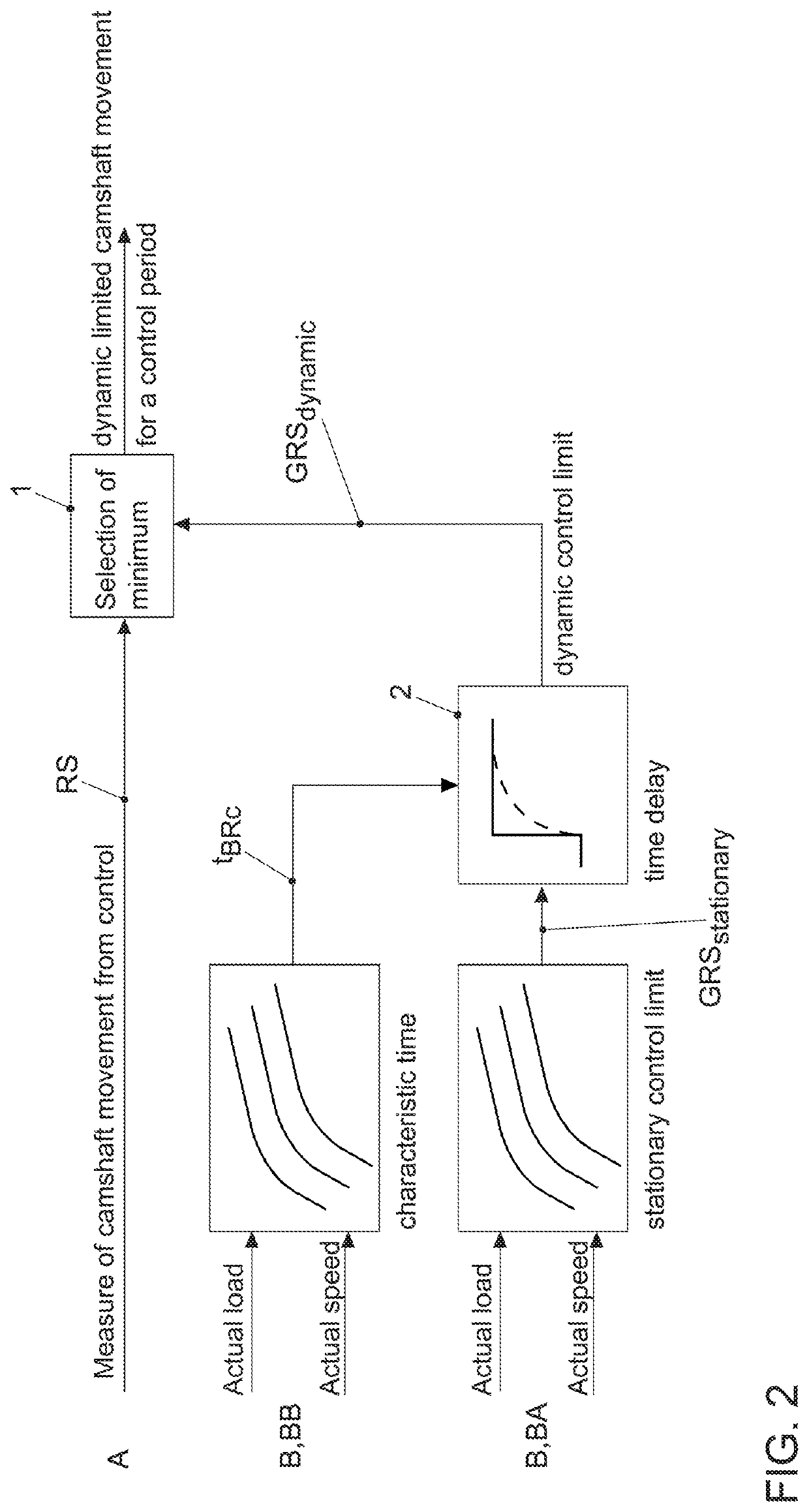
[0020]The pressure in the intake system is at least partially controlled and / or achieved with the aid of an exhaust-gas turbocharger that is present; in particular, through the method according to the invention the sluggishness of the internal combustion engine is avoided in the case of load jumps, especially load increases, wherein the method according to the invention can in particular be implemented in an internal combustion engine designed as an Otto engine. A control and / or regulating circuit is now provided, wherein at least one first circuit element designed as a comparing element and at least one second circuit element designed as a time delay element are present.
[0025]As explained above, the regulating control value curve is fundamentally stored in the engine control unit. The other curves and / or control values / values can also be stored and / or calculated in the engine control unit, in particular with the aid of a data memory and / or microprocessor. The corresponding regulation and / or control or the method according to the invention can thus be implemented in particular with the aid of the engine control unit and / or of a microprocessor or microcomputer. As a result, the abovementioned disadvantages are avoided, and corresponding advantages are achieved.

Problems solved by technology

The tendency of the internal combustion engine to knock, so-called “engine knocking,” arises in particular with high gas temperatures in the combustion chamber, which can lead to irregular combustion events, and in particular even to possible engine damage.
In the methods known in the prior art, in particular for controlling and / or regulating the operation of an internal combustion engine of a motor vehicle, which in particular work at least partially according to the Miller cycle, some of these methods are still not optimally developed.
As practice has demonstrated, however, dynamic intake camshaft movement based on the above-described difference sometimes is still not optimal or is problematic, because depending on the specific load jump and / or the history of the engine the raising of the above-mentioned effective compression can increase the engine's tendency toward irregular combustion events, and in particular can increase the tendency of the internal combustion engine to knock, or so-called “engine knocking” can then occur.
However, as a result of the deactivation of the intake camshaft movement, it is also no longer possible then for the full potential in establishing the charging of the air / fuel mixture in the combustion chamber to be increased or achieved.

Method used


Image

  • Method for controlling and/or regulating the operation of an internal combustion engine
  • Method for controlling and/or regulating the operation of an internal combustion engine

Examples


Embodiment Construction

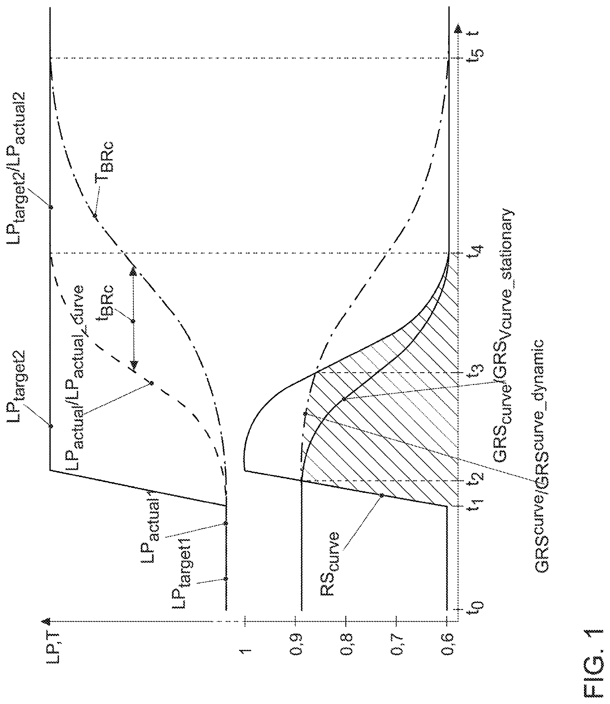
[0030]FIGS. 1 and 2 show—at least partially—an exemplary method according to the invention for controlling and / or regulating the operation of an internal combustion engine, in particular of an internal combustion engine of a motor. In this case the internal combustion engine is, in particular, at least partially controlled and / or regulated according to the Miller cycle.

[0031]FIG. 1 shows a load jump, namely a load increase of the internal combustion engine, over the course of the time t. In the case of an internal combustion engine, multiple different target load points and / or actual load points of the internal combustion engine can be applied in a known manner, in particular by an appropriate actuation of the accelerator pedal.

[0032]FIG. 1 shows here a load jump, namely a load increase of the internal combustion engine to a specific, higher, second target load point LPTarget2 starting from at least one specific applied, lower target load point LPTarget1 and / or starting from a first...


PUM


Abstract

A method for controlling and / or regulating the operation of an internal combustion engine, wherein the relevant specific relative locations of the intake camshaft with respect to the crankshaft are defined and / or controlled with the aid of regulating control values of the engine control unit, in particular for controlling the intake valves between the control value 1 for late and the control value 0 for early, and wherein a specific regulating control value curve and / or specific regulating control values for controlling the relative position of the intake camshaft is or are stored, at least for a specific control period for implementing the load jump, namely at least between the time of the start of the target load jump to the time of the end of the actual load jump corresponding to the target load jump.

Description

[0001]This nonprovisional application claims priority under 35 U.S.C. § 119(a) to German Patent Application No. 10 2018 212 247.4, which was filed in Germany on Jul. 24, 2018 and which is herein incorporated by reference.BACKGROUND OF THE INVENTIONField of the Invention[0002]The present invention relates to a method for controlling and / or regulating the operation of an internal combustion engine, in particular an internal combustion engine of a motor vehicle, in particular working at least partially according to the Miller cycle.Description of the Background Art[0003]In the prior art, firstly, different methods for controlling and / or regulating the operation of an internal combustion engine are known, in particular including the so-called “Miller-cycle engine” or internal combustion engine that is operated according to the so-called Miller cycle. In engines including such “Miller-cycle engines,” the relative location or positioning of an intake camshaft with respect to a crankshaft ...

Claims


Application Information

Patent Timeline
Patent Type & Authority Patents(United States)
IPC IPC(8): F02D13/02F02D41/24F02D41/00
CPCF02D13/0238F02D13/0269F02D41/0007F02D41/2438F02D2200/602F02D13/0234F02D41/10F02D2041/001F02D2041/1431Y02T10/12
Inventor THALER, TIM
Owner VOLKSWAGEN AG
Learn More