
Advanced unmanned aerial vehicle system

a technology of unmanned aerial vehicles and vehicles, applied in the field of advanced unmanned aerial vehicle systems, can solve the problems of inherently high vibration, limited range and payload capacity of rotary-wing aircraft, and achieve the effects of reducing their responsiveness, high degree of specialized training, and being readily available and quick to deploy

Inactive Publication Date: 2008-12-23
PARSONS JOHN CHARLES
View PDF15 Cites 25 Cited by
  • Summary
  • Abstract
  • Description
  • Claims
  • Application Information

AI Technical Summary

Benefits of technology

[0015](a) They require delivery and setup time. They must be called-in, unpacked and assembled. This dramatically reduces their responsiveness.
[0016](b) They require dedicated crews of three or four at the low end to as many as twenty or more to operate the large, sophisticated “Predator™” (a trademark of General Atomics Aeronautical Systems, Inc. for unmanned aerial vehicles) built by General Atomics Aeronautical Systems, Inc.
[0017](c) Their operators require a high degree of specialized training to use each specific UAV system.
[0018](d) The cost of these systems range from a high of $20 million for the aforementioned “Predator™” (a trademark of General Atomics Aeronautical Systems, Inc. for unmanned aerial vehicles) to a low of $250,000 for the “Raven™” (a trademark of AeroVironment, Inc. for unmanned aerial vehicles) built by AeroVironment, Inc. (Kerstein, “Boston Herald, May 11, 2005). These systems are expensive.
[0019](e) In an attempt to make UAV's more readily available and quicker to deploy, they have been scaled down. For example, the aforementioned “Raven™” (a trademark of AeroVironment, Inc. for unmanned aerial vehicles) has a wingspan of only 4.5 feet. This small size, however, creates serious disadvantages. Small airfoils mean small payloads and shorter ranges.
[0020](f) Fixed-wing UAV's take a lot of time getting to an operational altitude and can take considerable time going to their intended targets. Small fixed-wing UAV's are particularly slow, flying at only 20-60 mph. Large, powerful motors and the extra energy used by high speed flight are too heavy for small UAV's.

Problems solved by technology

Rotary-wing aircraft have proven unsatisfactory because of their high rate of energy consumption which limits range and payload capacity.
They also have inherently high levels of vibration which causes problems for sensor payloads.
As they tend to be vulnerable targets and are slow to take up position, lighter-than-air UAV's have had very limited use.
Many UAV's designed on the fixed-wing planform have become so expensive they have begun to defeat one of their basic design functions: protecting expensive aircraft.
This problem has become so pervasive that the more costly UAV's have been modified to carry so-called “parasite” UAV's.
Using a very expensive UAV to position an inexpensive one is not a satisfactory solution to cost problems.
Both these systems have common deficiencies.
Both systems also suffer because they induce tremendous G-forces on their payloads: as much as 17,000 G's for the artillery gun and 7,000 G's for the mortar.
These ultra-high G-forces create engineering, construction and materials problems.
The complexity of this invention with the resultant high cost leave it at a competitive disadvantage.
MAV's have not proven to be satisfactory as yet due to cost issues, reliability issues and durability issues.
The over-riding problem with MAV's is their inability to carry useful sized payloads.
(a) They require delivery and setup time. They must be called-in, unpacked and assembled. This dramatically reduces their responsiveness.
(b) They require dedicated crews of three or four at the low end to as many as twenty or more to operate the large, sophisticated “Predator™” (a trademark of General Atomics Aeronautical Systems, Inc. for unmanned aerial vehicles) built by General Atomics Aeronautical Systems, Inc.
(c) Their operators require a high degree of specialized training to use each specific UAV system.
(d) The cost of these systems range from a high of $20 million for the aforementioned “Predator™” (a trademark of General Atomics Aeronautical Systems, Inc. for unmanned aerial vehicles) to a low of $250,000 for the “Raven™” (a trademark of AeroVironment, Inc. for unmanned aerial vehicles) built by AeroVironment, Inc. (Kerstein, “Boston Herald, May 11, 2005). These systems are expensive.
(e) In an attempt to make UAV's more readily available and quicker to deploy, they have been scaled down. For example, the aforementioned “Raven™” (a trademark of AeroVironment, Inc. for unmanned aerial vehicles) has a wingspan of only 4.5 feet. This small size, however, creates serious disadvantages. Small airfoils mean small payloads and shorter ranges.
(f) Fixed-wing UAV's take a lot of time getting to an operational altitude and can take considerable time going to their intended targets. Small fixed-wing UAV's are particularly slow, flying at only 20-60 mph. Large, powerful motors and the extra energy used by high speed flight are too heavy for small UAV's.
(g) When not in use, today's UAV's are burdensome at best and truly logistically problematic for the larger models.
(h) Presently deployed UAV's cannot independently place sensors where they cannot land and they can land only in locations where there are specialized retrieval systems.

Method used


Image

  • Advanced unmanned aerial vehicle system
  • Advanced unmanned aerial vehicle system
  • Advanced unmanned aerial vehicle system

Examples


Embodiment Construction

FIGS. 1-7—Preferred Embodiment

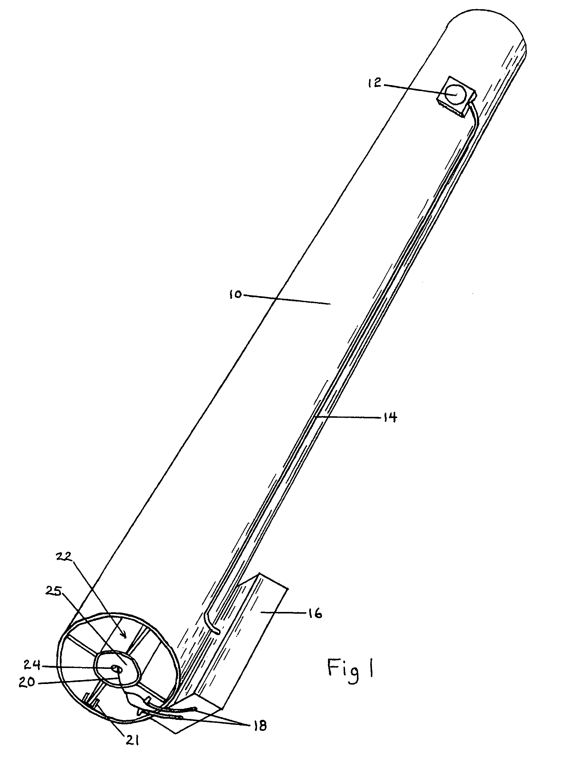
[0044]FIG. 1 shows a perspective view of a preferred embodiment of my UAV. In this basic version, a tube 10 is a container and a launcher for a rocket 22. The tube 10 is internally dimensioned to receive the rocket 22. A switch 12 is connected to a battery (not shown) in a battery holder 16 by firing switch wiring 14. A pair of electrical leads 18 connect the battery (not shown) in the battery holder 16 to an igniter 20 located in a rocket motor exhaust nozzle 24 at the aft end of a rocket motor 25. A stop 21 holds one of a set of four fins 30, securing the rocket 22 in the tube 10. (Note the large square area of the fins 30 which will be described at length below).

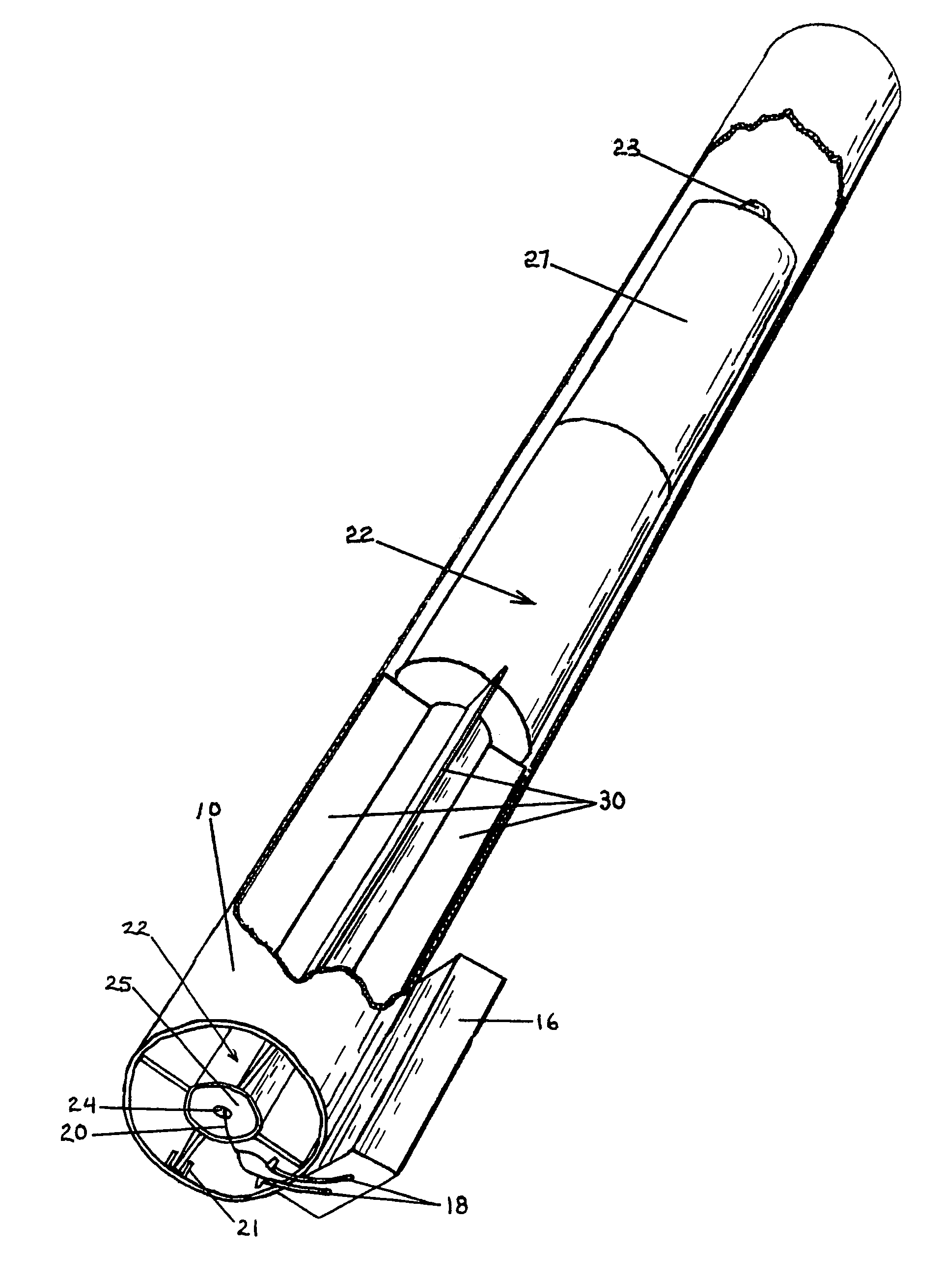
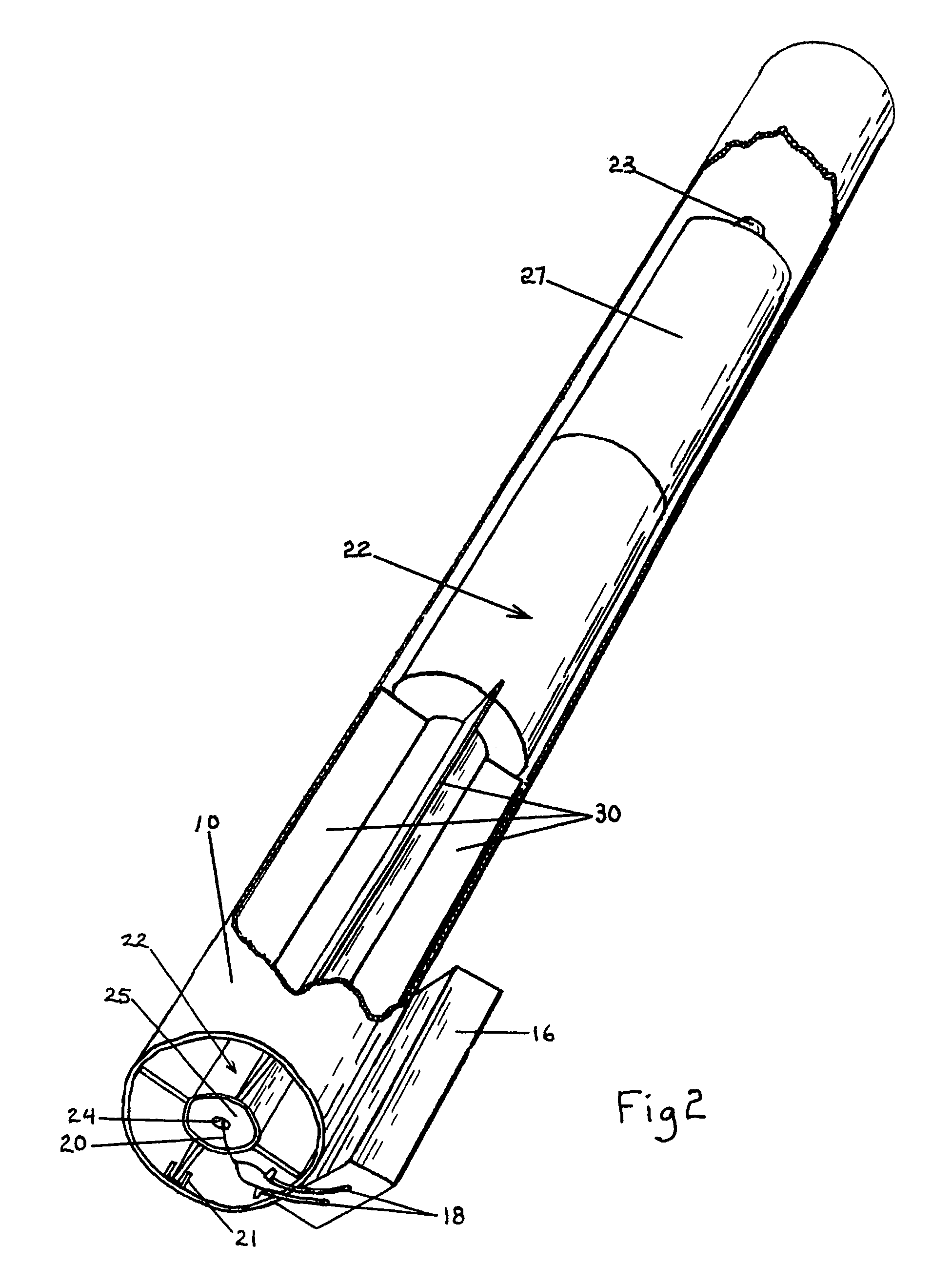
[0045]FIG. 2 is the same view as FIG. 1 with a cutaway revealing more of the rocket 22 including the extra large fins 30 and an aerodynamic feature 23 on the blunt nose.

[0046]FIG. 3 shows a perspective view of the rocket 22 with cutaways revealing a payload bay 26 in the payload section 27 an...


PUM


Abstract

An Unmanned Aerial Vehicle (UAV) system that couples the speed and responsiveness of a shoulder-launched rocket with the stable, slow-moving aerial platform of a parafoil is disclosed. The unique use of an over-damped rocket automatically positions the parafoil upwind of its target and overcomes the inherent inability of the parafoil to make headway in adverse wind conditions. This marriage of a rocket and a parafoil creates a valuable new synergy that allows the rocket to very quickly position a payload at altitude and defeat any adverse winds, while the parafoil provides an inexpensive and easy-to-fly vehicle for reconnaissance or accurately placing a payload on a target. The system is suitable for aerial videography, thermal imagery, target designation, sensor placement or precision munitions delivery; and can perform these functions at a small fraction of the cost of any other UAV. Unlike other UAV's, no flying skills are required of the operator. The system is so simple to use that no special training is required even for flying at night, and the intrinsic stability of the parafoil eliminates the need for avionic control systems.

Description

CROSS-REFERENCE TO RELATED APPLICATIONS[0001]This is a continuation of application Ser. No. 11 / 201,124 filed 8 Aug. 2005, now abandoned.FEDERALLY SPONSORED RESEARCH[0002]Not Applicable.SEQUENCE LISTING OR PROGRAM[0003]Not Applicable.BACKGROUND OF THE INVENTION[0004]1. Field of Invention[0005]This invention relates to an improved unmanned aerial vehicle system.[0006]2. Discussion of Prior Art[0007]Military forces have come to rely on Unmanned Aerial Vehicles (UAV's) to conduct reconnaissance and surveillance missions when those missions may endanger a flight crew and their aircraft.[0008]Many aircraft types have been adapted for unmanned operation including fixed-wing, rotary-wing and lighter-than-air. Rotary-wing aircraft have proven unsatisfactory because of their high rate of energy consumption which limits range and payload capacity. They also have inherently high levels of vibration which causes problems for sensor payloads.[0009]Lighter-than-air craft have been used as UAV's, l...

Claims


Application Information

Patent Timeline
Patent Type & Authority Patents(United States)
IPC IPC(8): F41G7/30B64D17/00F41G7/00
CPCF42B10/56F42B12/365
Inventor PARSONS, JOHN CHARLES
Owner PARSONS JOHN CHARLES
Learn More