Electrical connector with reduce distance between electrical terminals

a technology of electrical terminals and connectors, which is applied in the direction of coupling contact members, fixed connections, coupling device connections, etc., can solve the problems that the allowed minimum distance between two adjacent electrical terminals cannot be reduced easily, and the mounting portion or the bending wings of the electrical terminals may possibly interfere with each other, so as to achieve the effect of reducing the distance between two adjacent electrical terminals and preventing interference between mounting portions

Active Publication Date: 2021-08-17
DONGGUAN LUXSHARE TECH CO LTD
View PDF44 Cites 1 Cited by
  • Summary
  • Abstract
  • Description
  • Claims
  • Application Information

AI Technical Summary

Benefits of technology

[0006]In order to further reduce the distance between two adjacent electrical terminals of the electrical connector, this disclosure discloses an electrical connector, the distance between two adjacent electrical terminals of the electrical connector is effectively reduced, and the electrical connector can be installed easily.
[0024]In one or more embodiments of this disclosure, the edge of the electrical terminal forms the bending wing for facilitating the fixation of the electrical terminal when the electrical terminal is installed to the seat of the electrical connector. Moreover, in each pair of the electrical terminals, the mounting portions are arranged in misalignment. Hence, when the mounting portions of paired electrical terminals come close to each other, the interference between the mounting portions can be prevented, thereby effectively reducing the distance between two adjacent electrical terminals. In one or more embodiments of this disclosure, the terminal bodies as well as the bending wings are arranged in misalignment, so that the distance between the two terminal bodies can be further reduced.

Problems solved by technology

When adjacent electrical terminals are aligned densely, the mounting portions or the bending wings of the electrical terminals may possibly interfere with each other.
As a result, the allowed minimum distance between two adjacent electrical terminals is restricted by the existence of the mounting portion or the bending wing, and the allowed minimum distance between two adjacent electrical terminals cannot be reduced easily.

Method used


Image

  • Electrical connector with reduce distance between electrical terminals
  • Electrical connector with reduce distance between electrical terminals
  • Electrical connector with reduce distance between electrical terminals

Examples


Embodiment Construction

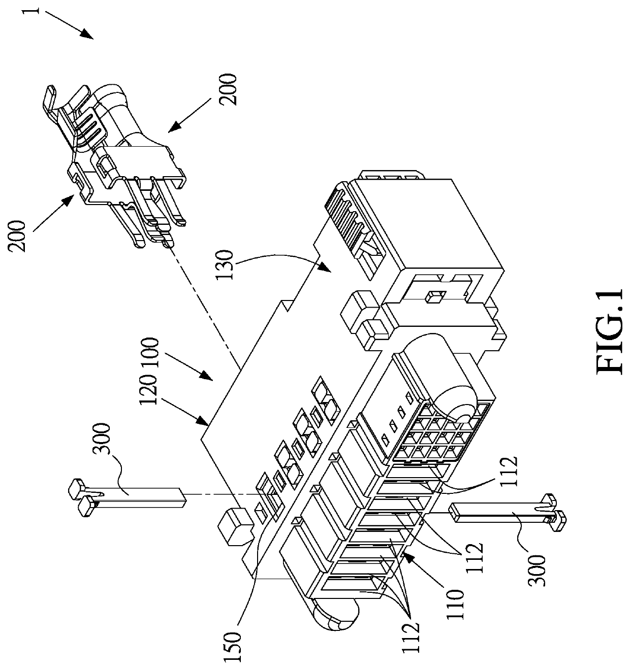
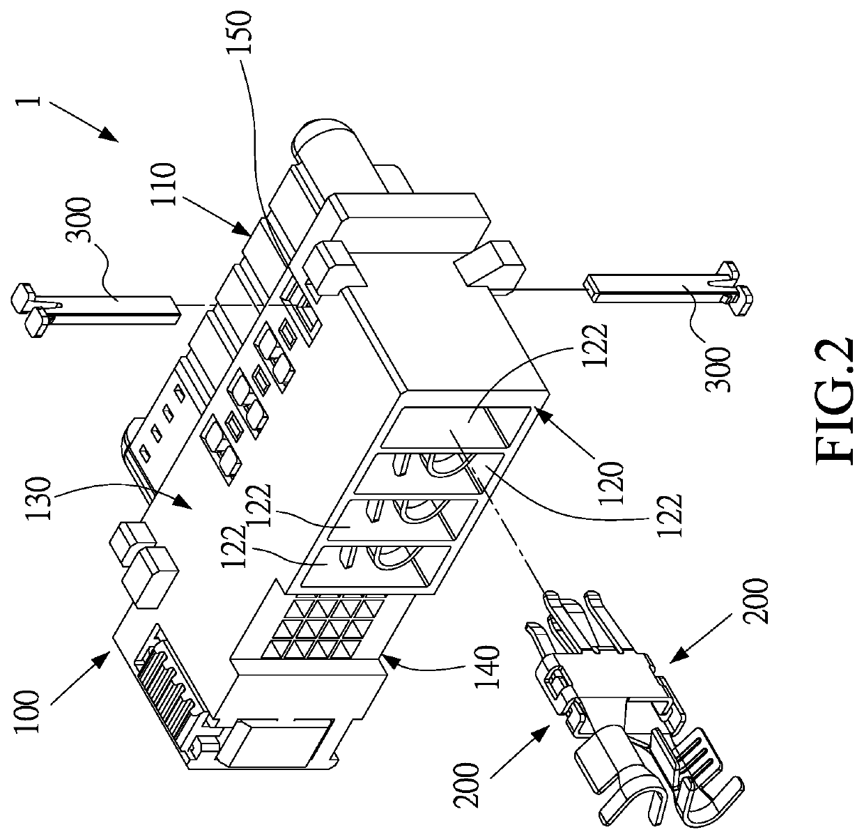
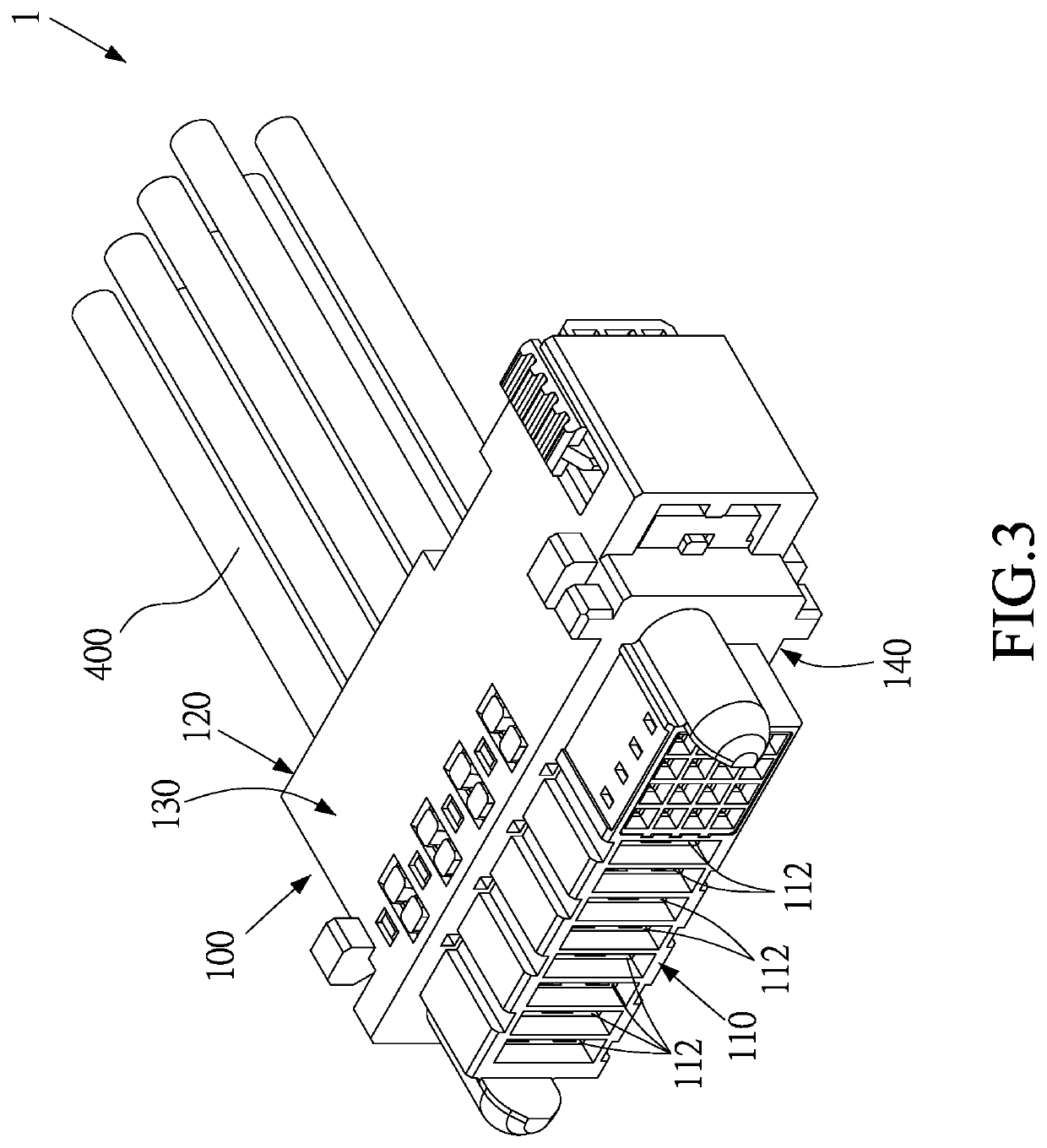
[0040]Please refer to FIG. 1, FIG. 2, and FIG. 3; an electrical connector 1 according to a first embodiment of this disclosure is illustrated. The electrical connector 1 comprises a seat 100 and two electrical terminals 200.

[0041]As shown in FIG. 1, FIG. 2, and FIG. 3, the seat 100 includes a front surface 110, a rear surface 120, a top surface 130, and a bottom surface 140. The front surface 110 and the rear surface 120 are opposite to each other. The top surface 130 and the bottom surface 140 are opposite to each other, and the top surface 130 and the bottom surface 140 are connected to the front surface 110 and the rear surface 120. Plural installation troughs 122 are formed on the rear surface 120, and each of the installation troughs 122 communicates with the front surface 110 through two insertion holes 112.

[0042]As shown in FIG. 1, FIG. 2, and FIG. 3, the two electrical terminals 200 are disposed in the installation trough 122 and respectively inserted into the insertion hole...


PUM


Abstract

An electrical connector includes a seat and two electrical terminals. The two electrical terminals are disposed within the seat. Each electrical terminal includes a terminal body and a mounting portion. Each terminal body includes a front end, a rear end, and two lateral edges opposite to each other. The two lateral edges are connected to the front end and the rear end. The mounting portion is extending from the rear end. The terminal body further includes one or more bending wings formed on one of the two lateral edges. The bending wing is located on an inner side of the terminal body. The inner sides of the terminal bodies face each other, and the terminal bodies of the two electrical terminals are arranged in parallel, and the mounting portions of the electrical terminals are located at different heights so as to be arranged in misalignment.

Description

CROSS-REFERENCE TO RELATED APPLICATION[0001]This non-provisional application claims priority under 35 U.S.C. § 119(a) to Patent Application No. 108139985 in Taiwan, R.O.C. on Nov. 4, 2019, the entire contents of which are hereby incorporated by reference.BACKGROUNDTechnical Field[0002]This disclosure relates to an electrical connector, in particular, to an electrical connector with reduced distances between electrical terminals.Related Art[0003]An electrical connector, for example a connector on a circuit board for power or signal transmissions, generally includes an electrical-insulated base and plural electrical terminals. The electrical terminals are provided for contacting external terminals. Depending on different types of external terminals, the electrical terminals will have different forms as well.[0004]An electrical terminal used for power transmission is usually configured as a plate-shape structure, thereby increasing the contact area between the electrical terminal of th...

Claims


Application Information

Patent Timeline
Patent Type & Authority Patents(United States)
IPC IPC(8): H01R12/58H05K3/30H01R12/70H01R13/502H01R13/629H01R13/26
CPCH01R12/58H01R12/7005H01R13/26H01R13/502H01R13/629H05K3/301H05K3/308H05K2201/10189H01R13/02H01R13/426H01R13/113
Inventor HUNG, YUNG-CHIH
Owner DONGGUAN LUXSHARE TECH CO LTD
Why Eureka
Try Eureka