Insulating profile, in particular for the production of window, door, and facade elements, and methods for the production thereof

a technology for insulating profiles and facade elements, which is applied in the field of insulating profiles, can solve the problems of high tool cost, lack of flexibility to react to certain desired changes in the adaptation of the composite geometry, and the inability to simply increase the visible width of the metal-plastic composite, etc., and achieves the effects of reducing tool cost, reducing complexity, and increasing quantity

Active Publication Date: 2021-07-27
ENSINGER
View PDF54 Cites 0 Cited by
  • Summary
  • Abstract
  • Description
  • Claims
  • Application Information

AI Technical Summary

Benefits of technology

[0039]In particular hereby, insulating profiles with highly accurate dimensions, i.e., small tolerances, and in particular high parallelism of the individual components of the insulating profile can be produced. This makes processing the insulating profiles to composite profiles considerably easier.
[0056]The concept of the present invention makes it possible, furthermore, to produce insulating profiles in which the insulating bar comprises second and optionally further functional elements that are integrally formed with the profile body, in addition to the first functional element or functional elements.
[0066]The separately produced elements of the insulating profile may be used not only for a specific geometry of an insulating profile. For example, the insulating bar of the insulating profile having a standardized overall height may be combined with different functional elements as required, and thus a wide range of profile geometries may be achieved, without a specific, in particular complex, extrusion tool having to be produced for each individual profile geometry.
[0067]Likewise, functional elements may be combined with differently structured insulating bars and thus the single functional element may be used in different insulating bars. This also minimizes tool costs.
[0068]Finally, due to the flexibility, achieved in accordance with the invention, in the use of the components, i.e., insulating bar / profile body and functional elements, an economic advantage may additionally be achieved, as the individual component parts or the components may be produced and used in lesser part complexity and in greater quantities.
[0072]The input of energy, the quality, and in particular the strength of the welding seam are controllable by appropriately designing the energy directors. It may thus also be controlled whether and how much melt is ejected from the joint zone.

Problems solved by technology

A further disadvantage of this classical method is, in addition to the high tool costs, the lacking flexibility to react to certain desired changes with regard to adaptations of the composite geometry.
Thus for example, one cannot simply increase the visible width of the metal-plastic composite while maintaining the insulating profile without losing out on the insulating effect.
To date, no system has emerged which fulfills all of these requirements.
A disadvantage of this method, though, is the necessity of so-called fastening catches on the base profile for the production of the clip connection, wherein said catches also invariably fix the fastening position of the hollow chamber to be formed.
However, it cannot be concluded from these publications how a metallic flag can be permanently fixedly attached without significantly degrading the thermal insulating effect and the mechanical properties, specifically the transverse tensile strength, for example according to DIN EN 14024.
Due to the thin wall thicknesses of film materials in combination with the described hollow chamber structure, products of that kind are clearly disadvantageous in case of fire in comparison with other solutions.
Free-standing thin plastic films also have the disadvantage that they are easily bendable.
In transporting and in storing products of that kind in a transport container, it is thus probable that flags made of free-standing foils buckle under the dead weight of the profiles, bend, and permanently deform.
All these variants described are not completely satisfying, which is why the object arises to propose an improved insulating profile which takes the stated problems and requirements into account.

Method used


Image

  • Insulating profile, in particular for the production of window, door, and facade elements, and methods for the production thereof
  • Insulating profile, in particular for the production of window, door, and facade elements, and methods for the production thereof
  • Insulating profile, in particular for the production of window, door, and facade elements, and methods for the production thereof

Examples


Embodiment Construction

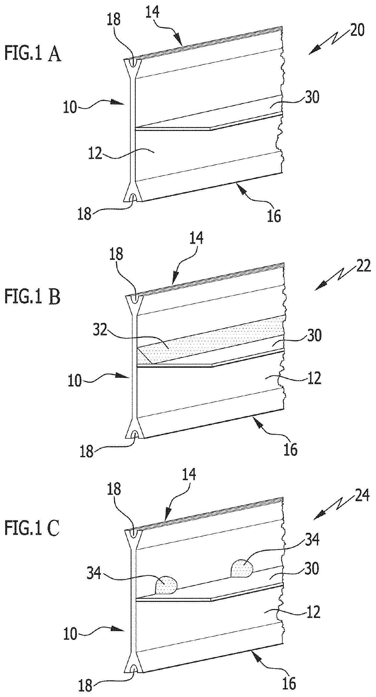
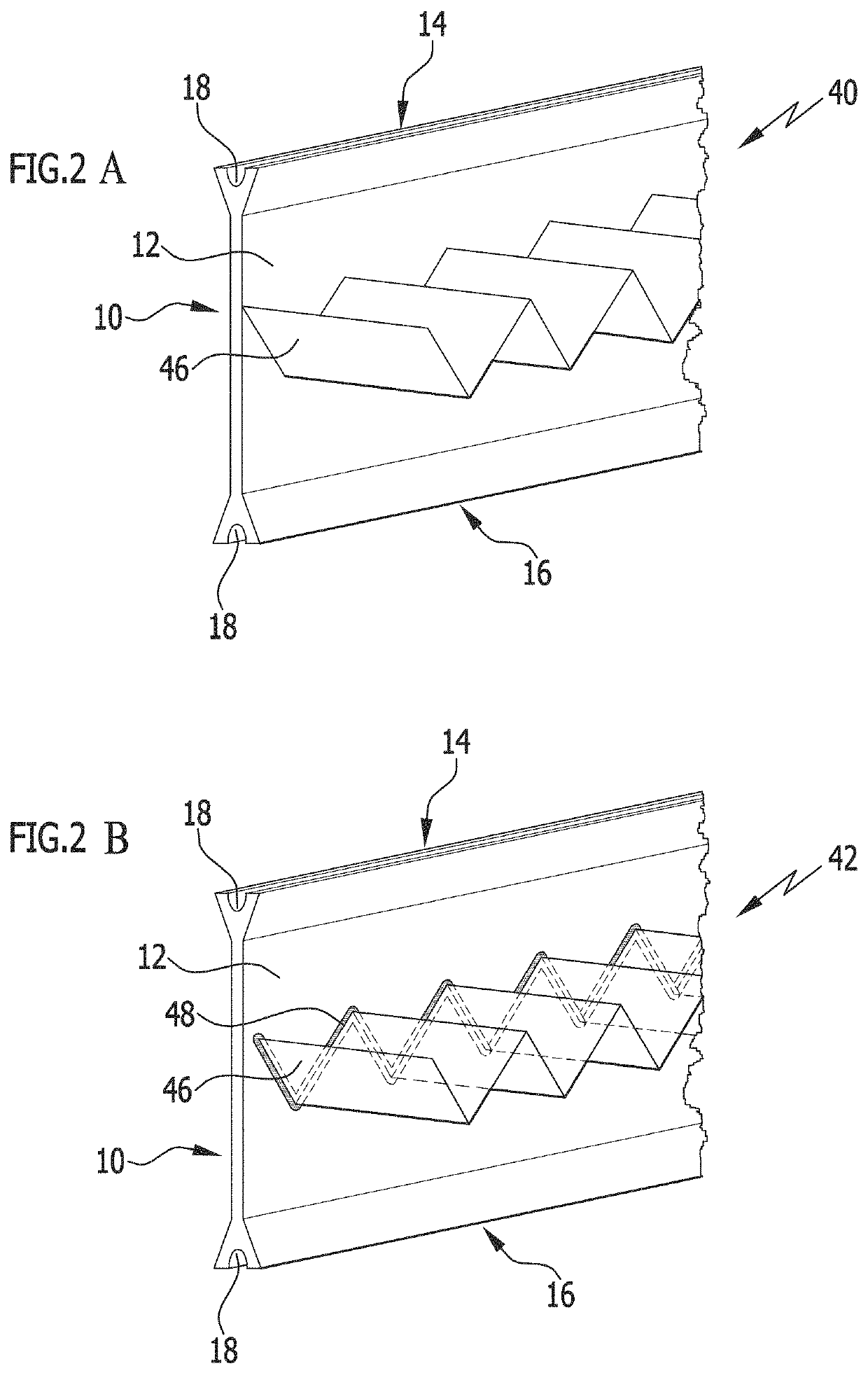
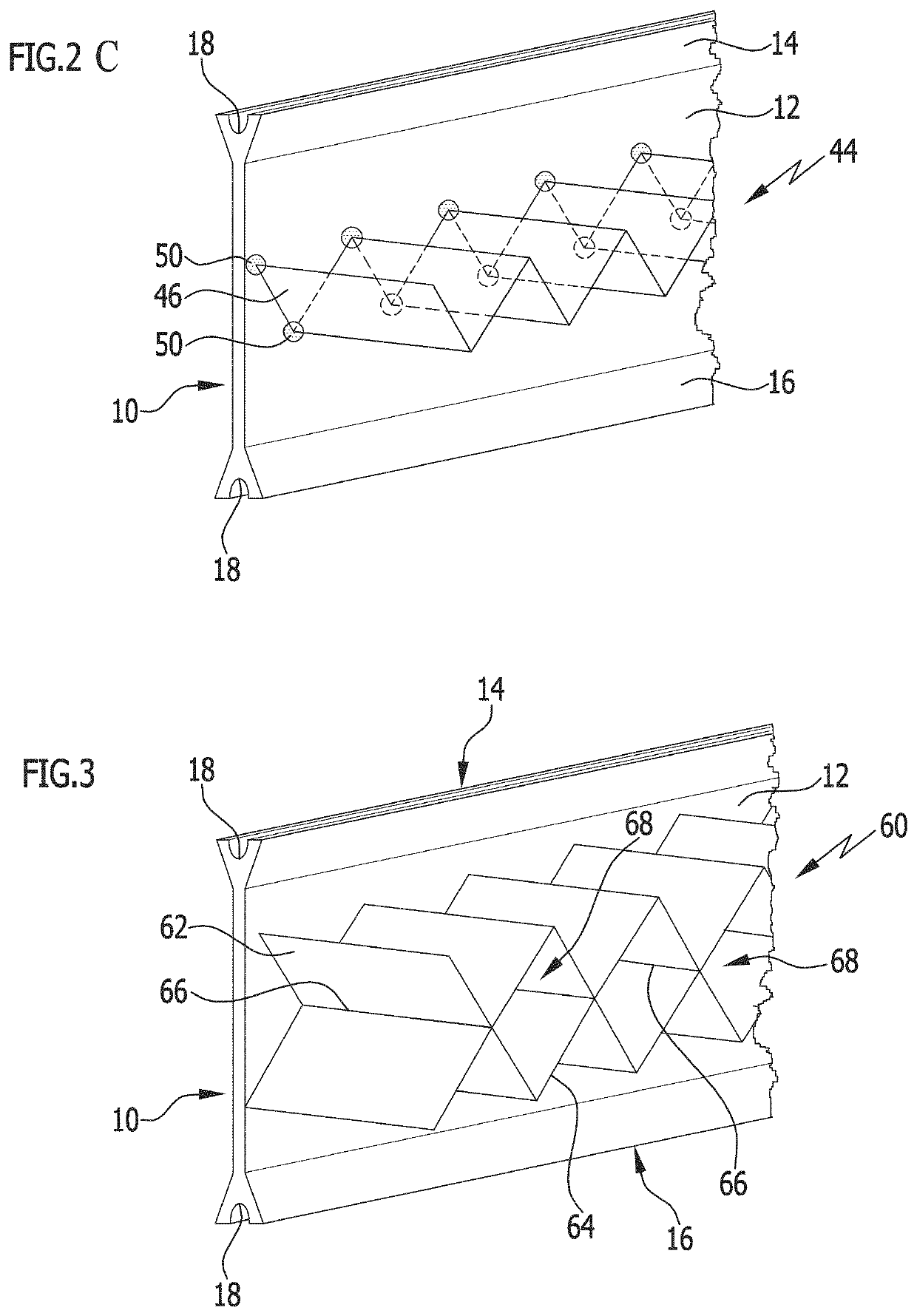
[0125]FIGS. 1A to 1C show a first embodiment of the insulating profiles in accordance with the invention in different variants, which each are based on an insulating bar 10 with a planar profile body 12. Adjoining the profile body 12 are rim sections 14, 16 which are configured as roll-in heads. The rim sections 14, 16 also extend in the longitudinal direction of the insulating profile in accordance with the invention and are formed on the outer rims of the profile body 12 at a distance transverse to the longitudinal direction. The production of such insulating bars 10 from a polymer material with a high degree of accuracy of the cross-sectional geometry and high linearity in one extruding step is economically possible without a great deal of expenditure. The extruding tools required for the process are of little complexity and are also available relatively economically.

[0126]When processing the insulating profile in accordance with the invention in the form of metal-plastic composi...


PUM

PropertyMeasurementUnit
thicknessaaaaaaaaaa
processing temperatureaaaaaaaaaa
temperatureaaaaaaaaaa

Abstract

The invention proposes insulating profiles of a polymer material, and methods for producing the insulating profiles, are disclosed.

Description

CROSS-REFERENCE TO RELATED APPLICATIONS[0001]This patent application is a continuation of International Patent Application No. PCT / EP2018 / 056742, filed on Mar. 16, 2018, which claims the benefit of German Patent Application No. 10 2017 107 684.0, filed on Apr. 10, 2017, which are incorporated herein by reference.BACKGROUND OF THE INVENTION[0002]The invention relates to insulating profiles of a polymer material, in particular for the production of window, door, and facade elements, and to methods for the production of the insulating profiles. The insulating profiles are used in particular in a variety of ways in the production of metal-plastic composite profiles, wherein the insulating profiles serve for the thermal and / or acoustic insulation of the composite profiles and typically connect two metal profiles to each other. The insulating profiles in accordance with the invention are used furthermore as so-called chicanes, which function as sills, for example in sliding systems for la...

Claims


Application Information

Patent Timeline
Patent Type & Authority Patents(United States)
IPC IPC(8): E06B3/263B29C65/48E04B1/74B29L31/00
CPCE06B3/2632B29C65/48E04B1/74B29L2031/003
Inventor HOPPMANN, SEVERINPAULUS, WOLFGANGAUBELE, SUSANN-MARIEELLWANGER, ROLANDROTHFUSS, MATTHIASMÖLLER, MICHAELSEHBURGER, AXEL
Owner ENSINGER
Why Eureka
Try Eureka