
System, method, and non-transitory computer-readable storage media related to correction of vision defects using a visual display

a visual display and display technology, applied in the field of vision defects correction, can solve the problems of ineffective attempts, large impact on the life of patients, and inability to read,

Active Publication Date: 2021-06-08
RAYTRX LLC
View PDF6 Cites 6 Cited by
  • Summary
  • Abstract
  • Description
  • Claims
  • Application Information

AI Technical Summary

Benefits of technology

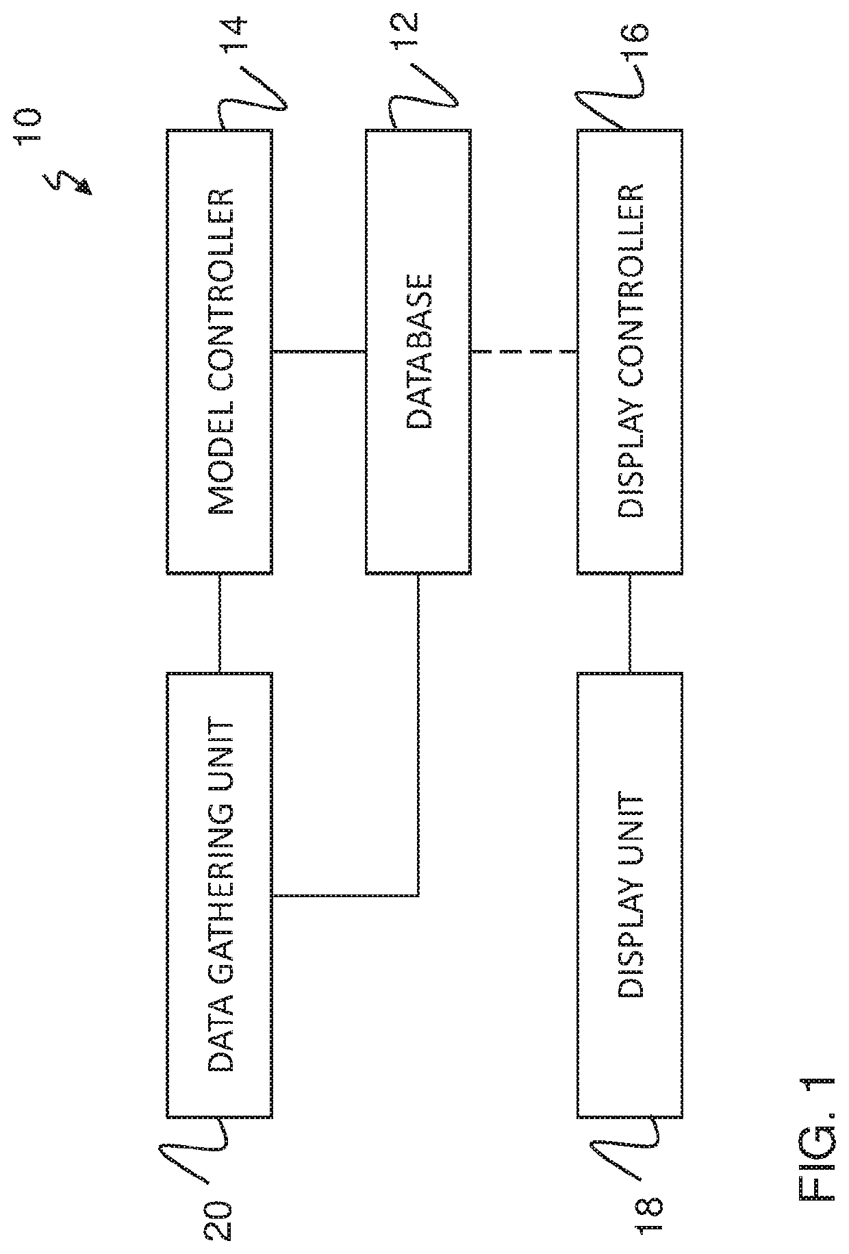
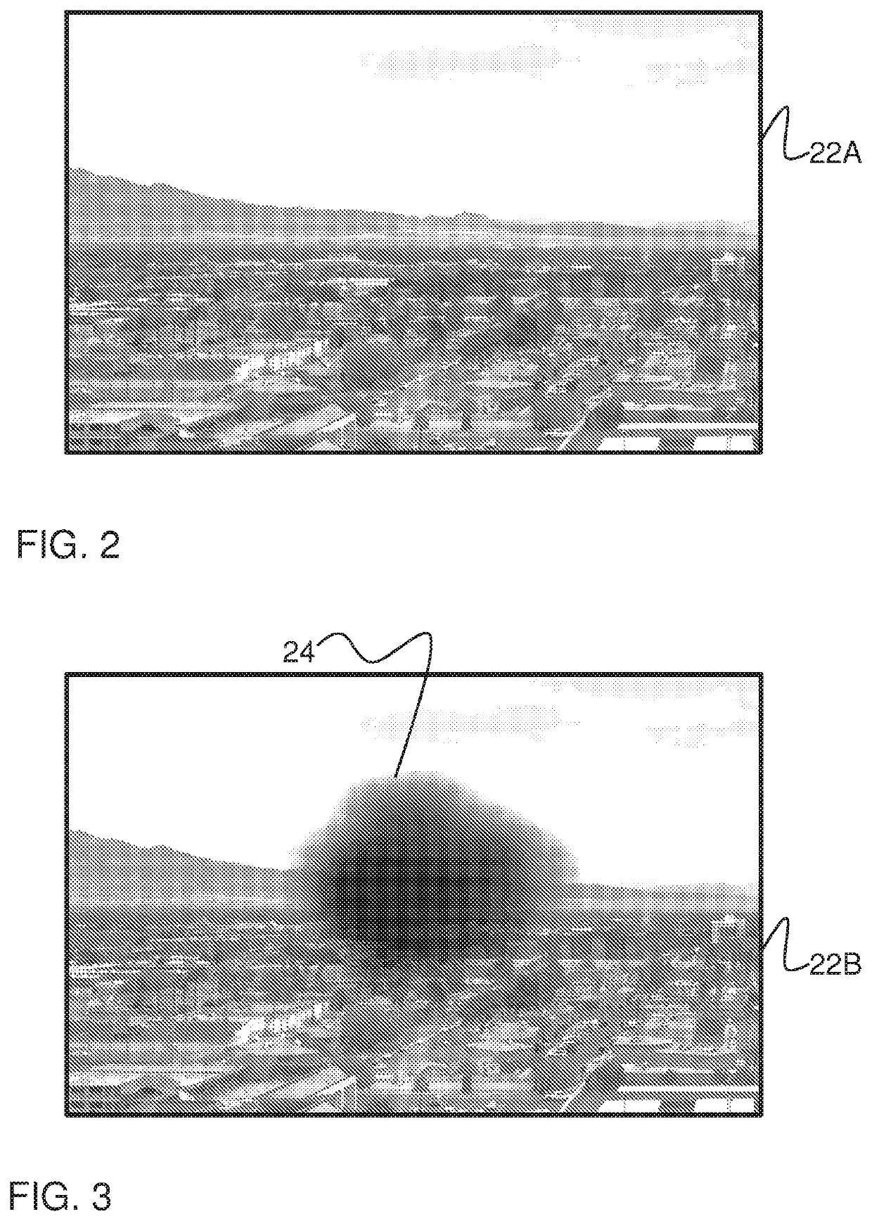
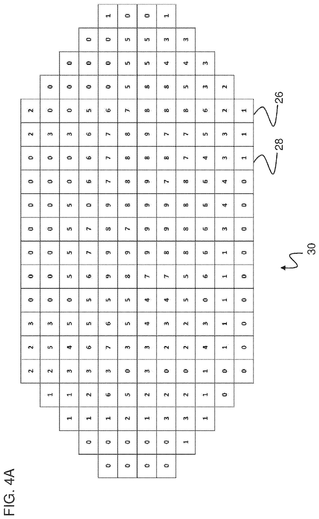
This patent describes a system, method, and computer-readable storage media for creating a special visual model of a patient's vision and applying corrections to the patient's image based on the visual model. The system includes a database, a model controller, a display controller, and a display unit. The model controller creates a visual model with data related to the patient's vision, including details about any areas that may need correction. The model controller then creates a boundary around these areas, which serves as a guide for the corrections that will be applied to the patient's image. The display controller receives the patient's image and uses the boundary and retinal map to make the corrections. The corrected image is then presented to the patient's eye. The technical effects of this system include improved vision, better quality of life, and improved treatment outcomes for patients with vision issues.

Problems solved by technology

The impact to a patient's life due to the loss of a portion of their vision is enormous, including degraded and loss of the ability to read, watch TV and see computer screens.
These attempts have not been very effective and are bulky and expensive.

Method used


Image

  • System, method, and non-transitory computer-readable storage media related to correction of vision defects using a visual display
  • System, method, and non-transitory computer-readable storage media related to correction of vision defects using a visual display
  • System, method, and non-transitory computer-readable storage media related to correction of vision defects using a visual display

Examples


Embodiment Construction

[0037]In the following description, numerous specific details are set forth in order to provide a thorough understanding of the present invention. It will be apparent, however, to one having ordinary skill in the art that the specific detail need not be employed to practice the present invention. In other instances, well-known materials or methods have not been described in detail in order to avoid obscuring the present invention.

[0038]Reference throughout this specification to “one embodiment”, “an embodiment”, “one example”, or “an example” means that a particular feature, structure or characteristic described in connection with the embodiment or example is included in at least one embodiment of the present invention. Thus, appearances of the phrases “in one embodiment”, “in an embodiment”, “one example”, or “an example” in various places throughout this specification are not necessarily all referring to the same embodiment or example. Furthermore, the particular features, structu...


PUM


Abstract

A method of at-home monitoring of eye conditions using a head mounted display that is capable of establishing a visual model associated with a patient. The visual model may include data related to a quality of the patient's vision. The patient may use the system to establish a visual model periodically, such as daily, and the system may compare the visual model to previous visual models and send an alert to the patient's physician if changes meeting a given criteria are detected. This may allow the physician to immediately take steps to save the patient's eyesight where a delay in treatment may result in vision loss.

Description

CROSS-REFERENCE TO RELATED APPLICATIONS[0001]This application is a continuation of U.S. patent application Ser. No. 17 / 137,093 filed Dec. 29, 2020, which is a continuation-in-part of U.S. patent application Ser. No. 16 / 173,719 filed Oct. 29, 2018, which claims priority to and the benefit of U.S. Patent Application Ser. No. 62 / 134,422, filed on Mar. 17, 2015, U.S. patent application Ser. No. 15 / 073,144 filed Mar. 17, 2016, and U.S. patent application Ser. No. 15 / 940,561 filed Mar. 29, 2018, the disclosures of which are hereby incorporated by reference.FIELD OF THE DISCLOSURE[0002]The present invention relates generally to the correction of vision defects, and more specifically, to a system, and methods for compensating for visual defects for detecting the vision defects, capturing an image, correcting the image and displaying a corrected image.BACKGROUND[0003]Macular degeneration and other FOV (Field of Vision) related blindness or vision defect conditions, such as end-stage glaucoma...

Claims


Application Information

Patent Timeline
IPC IPC(8): G06K9/00A61B3/14G16H30/40G16H10/60A61B3/032A61B3/024A61B3/00A61B3/12G16H50/20G16H30/20A61F9/08
CPCG16H30/40A61B3/0025A61B3/024A61B3/032A61B3/12G16H10/60G16H30/20G16H50/20A61F9/08G16H70/60
Inventor FREEMAN, RICHARD C.FREEMAN, MICHAEL H.FREEMAN, MITCHAEL C.BOSS, CHADBOSS, JORDAN
Owner RAYTRX LLC
Learn More