
Button assemblies

a technology of buttons and assemblies, applied in the direction of pulse techniques, electronic switching, electrical apparatus, etc., can solve the problems of weak generated electrical signals and difficult detection

Active Publication Date: 2021-06-01
SATECO AG
View PDF3 Cites 2 Cited by
  • Summary
  • Abstract
  • Description
  • Claims
  • Application Information

AI Technical Summary

Benefits of technology

The patent describes a method for creating a button assembly with a flexible film that contains piezoelectric material. When the film is stretched, the distance between dipolar particles in the film is reduced, resulting in an increase in the density of dipolar particles between the first and second electrodes. This increase in density induces an electric charge which is collected by the electrodes. The electric charge can be converted into a voltage signal, which can be sent to a digital interface for further use. The method can be used to create button assemblies with high sensitivity and durability.

Problems solved by technology

The electrical signal which is generated is proportional to the amount with the piezoelectric material is compressed; since the piezoelectric material is very difficult to compress the generated electrical signal will be weak and difficult to detect.

Method used


Image

  • Button assemblies
  • Button assemblies
  • Button assemblies

Examples


Embodiment Construction

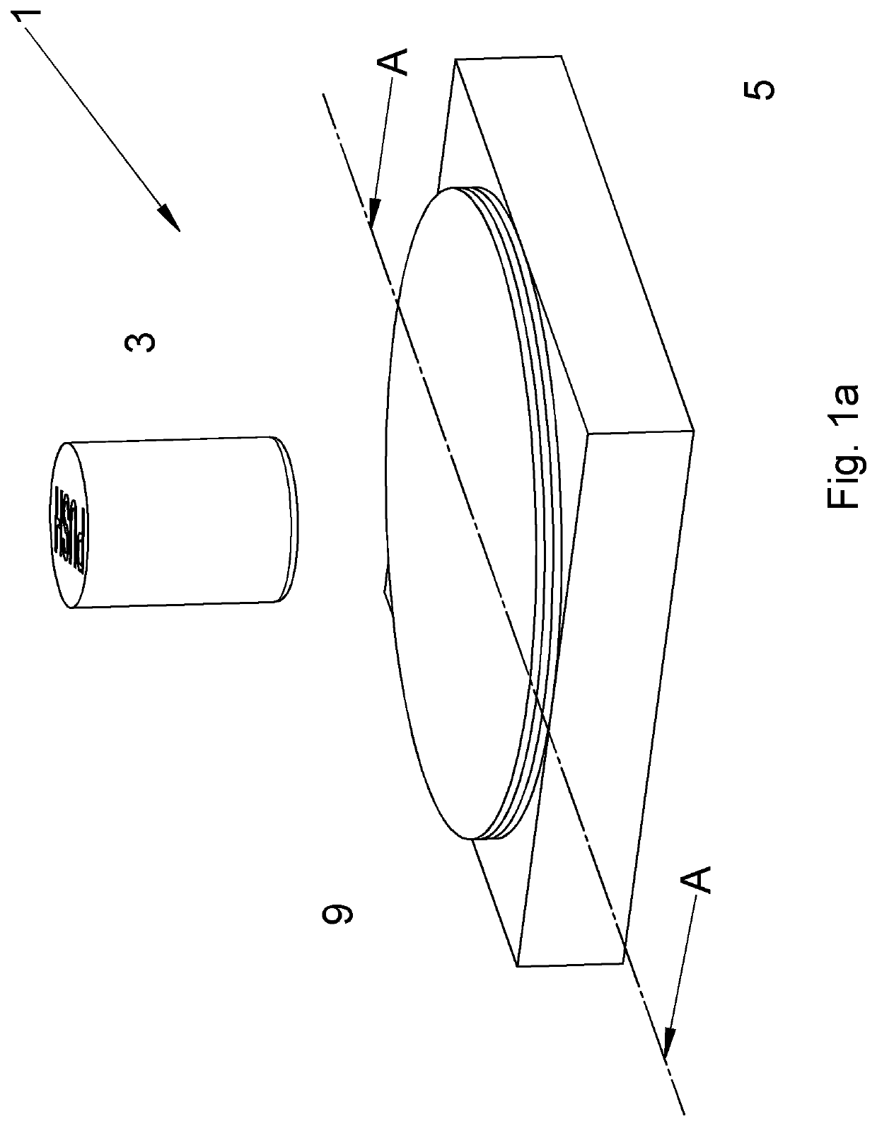
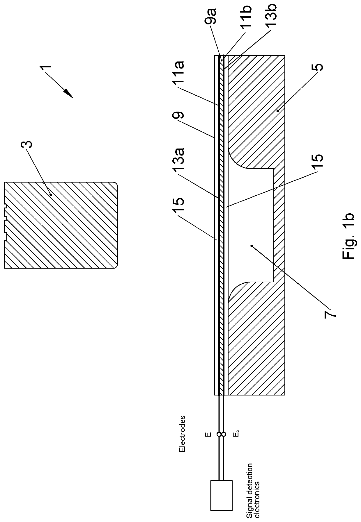
[0038]FIG. 1a provides a perspective view of a button assembly 1 according to an embodiment of the present invention; FIG. 1b provides a cross sectional view of the button of FIG. 1a taken along line A-A′ of FIG. 1a.

[0039]Referring to FIGS. 1a and 1b, the button assembly 1, comprises, an actuator member 3; a base member 5 having a cavity 7 defined therein which can receive a least a part of the actuator member 3; and a flexible film 9 which is arranged to overlay the cavity 7 in the base member 5, and is interposed between the base member 5 and the actuator member 3.

[0040]In this example the actuator member 3 comprises a nodule 3, and wherein the base member 5 has a cavity 7 defined therein which can receive a least a part of that nodule 3. However, it will be understood that the actuator member 3 may take any other suitable form. Preferably the base member 5 comprises a polymer, hard elastomer, semiconductor material or metal so that the base member 5 is stiff. Preferably the actu...


PUM


Abstract

According to the present invention there is provided a button assembly, comprising, an actuator member; a base member having a cavity defined therein which can receive a least a part of the actuator member; a flexible film which comprises piezoelectric material, wherein the piezoelectric material is preferably dipolar particles; a first electrode which is located between the piezoelectric material of the flexible film and the actuator member, and a second electrode which is located between the piezoelectric material of the flexible film and the base member, and wherein the flexible film is arranged to overlay the cavity in the base member, and to be interposed between the base member and the actuator member, such that moving at least a part of the actuator member into the cavity of the base member will cause the film to stretch thereby generating an electrical signal in the first and second electrodes.

Description

RELATED APPLICATIONS[0001]This application is a national phase of PCT / IB2017 / 056365, filed on Oct. 13, 2017, which claims the benefit of Swiss Application No. 01588 / 16, filed on Dec. 5, 2016. The entire contents of these applications are hereby incorporated by reference.FIELD OF THE INVENTION[0002]The present invention concerns button assemblies each of which uses piezoelectric material; in particular the present invention concerns button assemblies which comprises an elastic film comprising piezoelectric material, wherein the film is arranged to overlay a profiled surface, so that when a user presses the button assembly the film is stretched.DESCRIPTION OF RELATED ART[0003]A piezoelectric material is a material which has the ability to generate an electric charge in response to applied mechanical stress. Existing button assemblies which use piezoelectric material are typically designed to have a stiff top and bottom member, and a layer of piezoelectric material interposed between t...

Claims


Application Information

Patent Timeline
Patent Type & Authority Patents(United States)
IPC IPC(8): H03K17/96H01L41/08H10N30/00
CPCH03K17/964H01L41/08H03K2217/96015
Inventor KRAEMER, RONNYHAEFLIGER, DANIEL
Owner SATECO AG
Learn More