
High temperature composite structure and system for detecting degradation thereof

Active Publication Date: 2021-05-04
GOVERNMENT OF THE UNITED STATES AS REPRESENTED BY THE SEC OF THE AIR FORCE
View PDF15 Cites 1 Cited by
  • Summary
  • Abstract
  • Description
  • Claims
  • Application Information

AI Technical Summary

Benefits of technology

The invention describes a novel material called HTC which can be used in high-temperature environments. The material consists of a matrix made of ceramic and carbon, with fiber embedded in it. The fiber can take the form of woven or non-woven webs. The material also contains electrical conductors which can be in the form of metal wires or staples at different depths or orientations. The conductors can be made of various metals like niobium, molybdenum, ruthenium, rhodium, and others. The material can be used as a surface or structural component of an aircraft or other apparatus exposed to aggressive environments. The invention also includes a method for monitoring degradation of the material and remedying it based on the monitoring results. The technical effect of the invention is the provision of a material that can withstand high temperatures and has improved electrical conductivity.

Problems solved by technology

Other types of composites, such as polymer matrix composites (PMCs), typically cannot survive for any reasonable length of time in these environments.
PMCs are also formed at much lower temperatures than HTCs, at less than about 500° C., whereas HTCs are generally fabricated at temperatures greater than about 1100° C. Thus, the materials and methods that are applicable to PMCs are not applicable to HTCs.
In the absence of such inspections, a component might fail, leading to catastrophic damages.
Some of the structural problems that can occur are spalling, cracking, chemical reaction, and erosion (ablation).
However, removing such a component from use to perform the inspection can be expensive and time consuming.

Method used


Image

  • High temperature composite structure and system for detecting degradation thereof
  • High temperature composite structure and system for detecting degradation thereof
  • High temperature composite structure and system for detecting degradation thereof

Examples


specific embodiments

[0029]With reference now to the figures, various specific embodiments of the present invention are described.

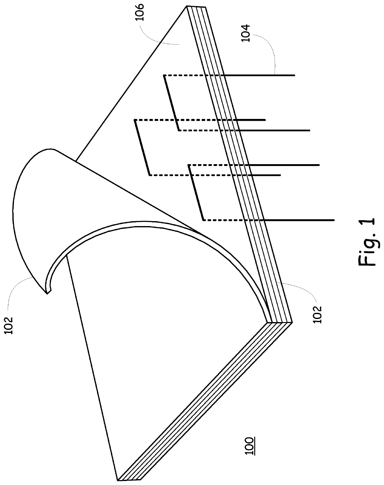
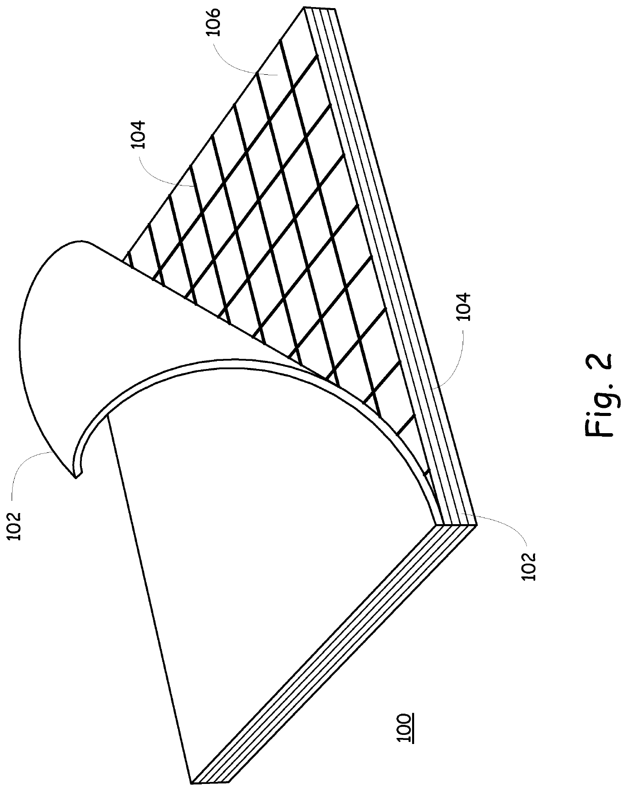
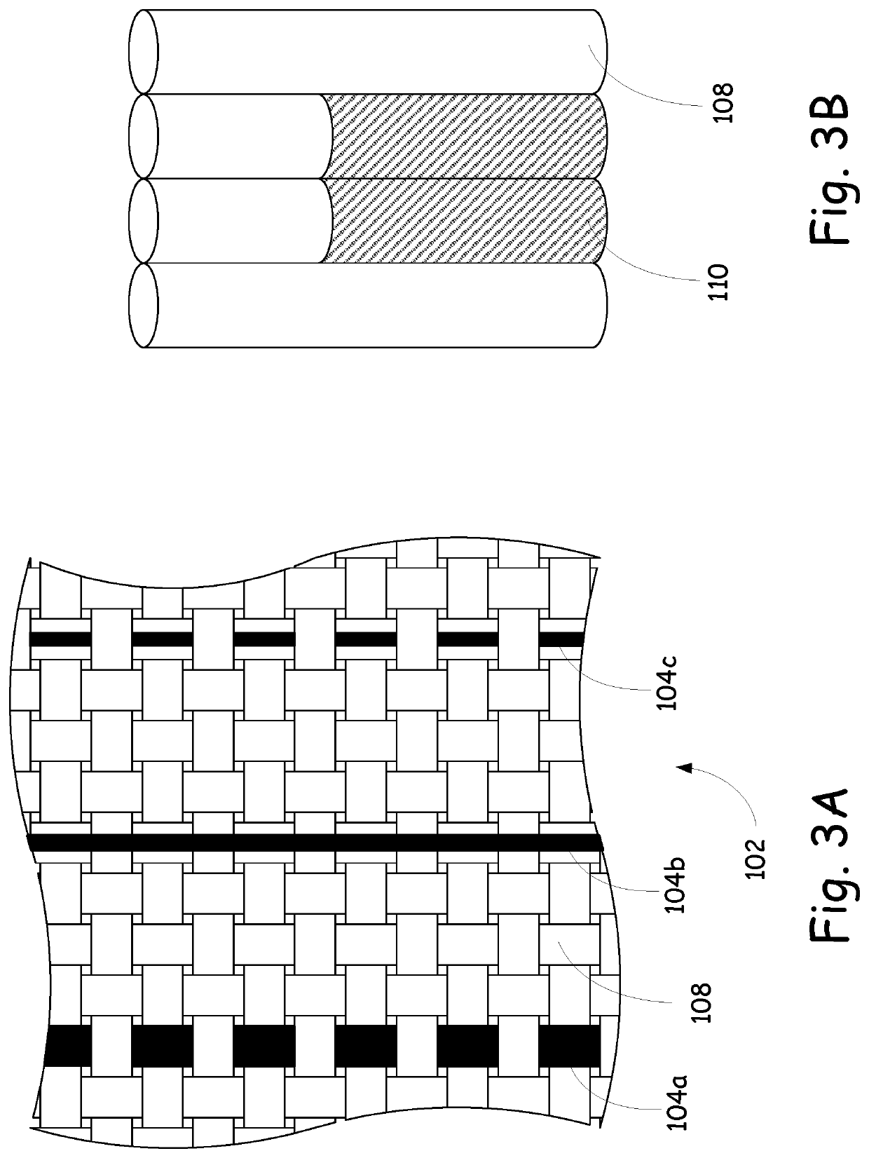
[0030]FIG. 1 depicts a lay-up 100 according to an embodiment of the present invention, with five plies 102 that have been infiltrated with a matrix 106. FIG. 1 and the other figures are highly representational, in that they show a top-most ply 102 curled back so as to reveal the electrical conductors 104 that are disposed either within an underlying ply 102 or between two adjacent plies 102. The number of plies 102 in the lay-up 100 is representational only, and not limiting. So too the number, shape, location, and depth of the electrical conductors 104 as depicted is representational only and not limiting.

[0031]In the embodiment of FIG. 1, the electrical conductors 104 take the form of electrically conductive wires that come up through the bottom of the lay-up 100 to one or more of a plurality of different levels and positions, in a configuration that generally resembles a s...


PUM

PropertyMeasurementUnit
Temperatureaaaaaaaaaa
Electrical conductivityaaaaaaaaaa
Volumeaaaaaaaaaa

Abstract

The present disclosure includes a system and method for monitoring degradation of a high temperature composite component (HTC). The HTC is defined by a volume that includes a matrix material and a fiber formed from at least one of ceramic and carbon material. One or more electrical conductors are disposed within the volume and connected directly or indirectly to a monitoring system.

Description

GOVERNMENT RIGHTS STATEMENT[0001]The invention described herein may be manufactured and used by or for the Government of the United States for all governmental purposes without the payment of any royalty.FIELD OF THE INVENTION[0002]This invention relates to the field of high temperature ceramic or carbon composites. More particularly, this invention relates to detecting the structural integrity of components made from such materials.BACKGROUND OF THE INVENTION[0003]The manufacturing process for a high temperature composite (HTC) typically consists of (1) lay-up and fixation of the fibers, shaped as the desired component (as used herein, the term lay-up also includes a preform, as described in more detail hereafter), (2) infiltration of the matrix material, and (3) curing and firing of the HTC to drive off volatile compounds, leaving just the HTC material remaining, namely fiber and matrix, with the latter being ceramic or carbon-based. The first and second steps can be iteratively r...

Claims


Application Information

Patent Timeline
IPC IPC(8): C04B35/622C04B111/94
CPCC04B35/62272C04B35/62231C04B2111/94C04B2235/40C04B2235/522C04B2235/5248C04B2235/5256C04B2235/5288C04B35/80C04B35/83C04B2235/5216C04B35/62876C04B2237/68C04B2235/5268
Inventor APOSTOLOV, ZLATOMIR D.
Owner GOVERNMENT OF THE UNITED STATES AS REPRESENTED BY THE SEC OF THE AIR FORCE
Learn More