Transmission, and control system for work vehicle
a technology for work vehicles and control systems, applied in the direction of fluid gearings, vehicle sub-unit features, gearings, etc., can solve problems such as efficiency reduction
- Summary
- Abstract
- Description
- Claims
- Application Information
AI Technical Summary
Benefits of technology
Problems solved by technology
Method used
Image
Examples
first embodiment
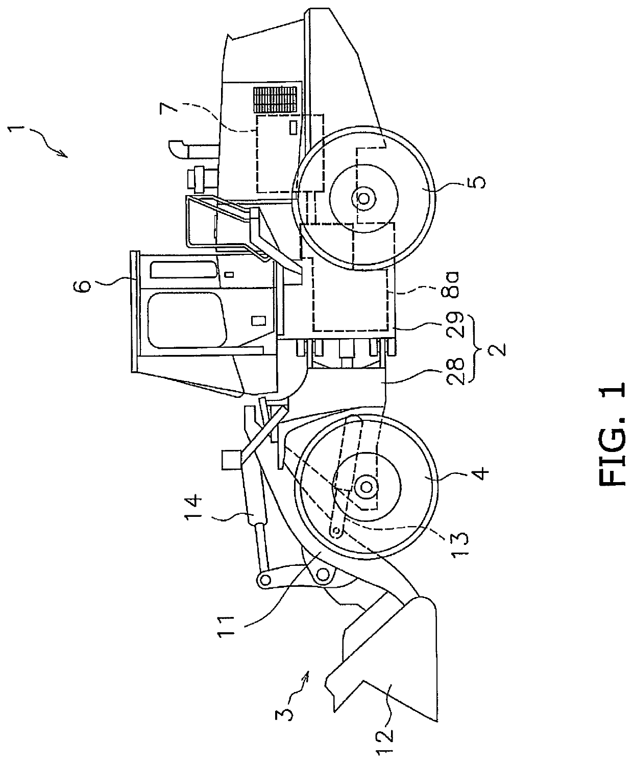
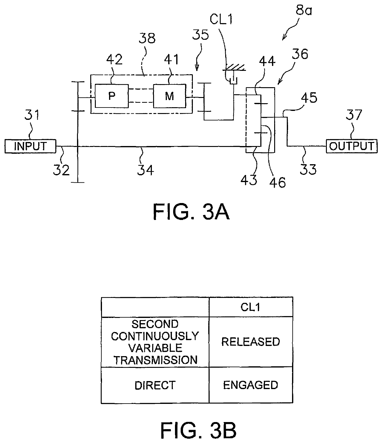
[0046]FIG. 3A is a schematic view of a configuration of the transmission 8a according to a As illustrated in FIG. 3A, the transmission 8a includes an input shaft 31, a first rotary shaft 32, a second rotary shaft 33, an output shaft 37, a first path 34, a second path 35, and a planetary gear mechanism 36 and a second element fixing clutch CL1.
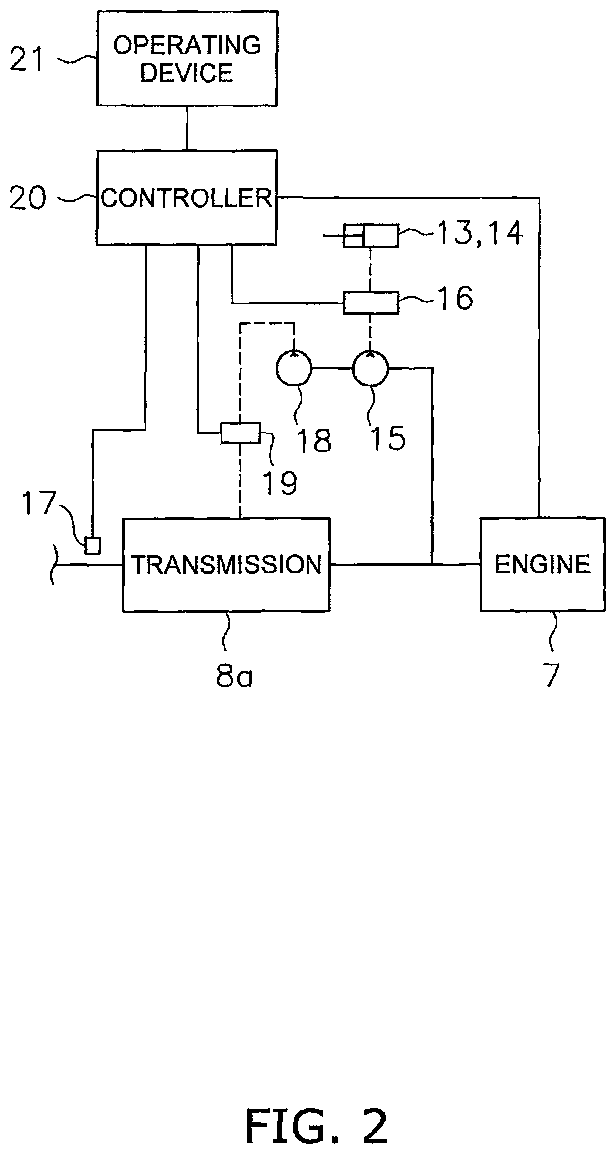
[0047]Rotational power from the engine 7 is input to the input shaft 31. The first rotary shaft 32 is connected to the input shaft 31. The first rotary shaft 32 may be integrated with the input shaft 31. Alternatively, the first rotary shaft 32 may be connected to the input shaft 31 through a gear or a clutch. The second rotary shaft 33 is connected to the output shaft 37. The second rotary shaft 33 may be integrated with the output shaft 37. Alternatively, the second rotary shaft 33 may be connected to the output shaft 37 through a gear or a clutch.
[0048]The first path 34 is disposed between the first rotary shaft 32 and the second rotary sha...
second embodiment
[0079]Next, a transmission 8f according to a first modified example of the second embodiment will be described. FIG. 8A is a schematic view of a configuration of the transmission 8f. FIG. 8B is a table illustrating the relationship between the mode of the transmission 8f and the state of the clutch.
[0080]As illustrated in FIG. 8A, the transmission 8f further includes the first path disconnect clutch CL2 as compared to the transmission 8e according to the second embodiment. The first path disconnect clutch CL2 is the same as that according to the first modified example of the first embodiment.
[0081]As illustrated in FIG. 8B, when the element coupling clutch CL4 is in the engaged state and the first path disconnect clutch CL2 is in the released state, the transmission 8f transmits rotational power from the engine 7 in the first continuously variable transmission mode. When the element coupling clutch CL4 is in the released state and the first path disconnect clutch CL2 is in the engag...
third embodiment
[0090]Next, a transmission 8i will be described. FIG. 11A is a schematic view of a configuration of the transmission 8i. FIG. 11B is a table illustrating the relationship between the mode of the transmission 8i and the state of the clutch.
[0091]As illustrated in FIG. 11A, the transmission 8i includes the first path disconnect clutch CL2 and the first element fixing clutch CL3. The first path disconnect clutch CL2 and the first element fixing clutch CL3 are the same as those according to the first modified example of the first embodiment. However, the transmission 8i does not include the second element fixing clutch CL1.
[0092]As illustrated in FIG. 11B, when the first path disconnect clutch CL2 is in the released state and the first element fixing clutch CL3 is in the engaged state, the transmission 8i transmits rotational power from the engine 7 in the first continuously variable transmission mode. When the first path disconnect clutch CL2 is in the engaged state and the first elem...
PUM
 Abstract
Description
Claims
Application Information
 - R&D Engineer
- R&D Manager
- IP Professional
- Industry Leading Data Capabilities
- Powerful AI technology
- Patent DNA Extraction
Browse by: Latest US Patents, China's latest patents, Technical Efficacy Thesaurus, Application Domain, Technology Topic, Popular Technical Reports.
© 2024 PatSnap. All rights reserved.Legal|Privacy policy|Modern Slavery Act Transparency Statement|Sitemap|About US| Contact US: help@patsnap.com


