
Additive manufacturing of three-dimensional articles

a three-dimensional article and additive manufacturing technology, applied in the direction of additive manufacturing processes, manufacturing tools, auxillary shaping apparatuses, etc., can solve the problems of destroying the cathode element and/or the electronics connected, and affecting the reliability of the additive manufacturing process. , to achieve the effect of simple and inexpensive implementation and improved reliability of the additive manufacturing process

Active Publication Date: 2021-04-27
ARCAM AB
View PDF315 Cites 0 Cited by
  • Summary
  • Abstract
  • Description
  • Claims
  • Application Information

AI Technical Summary

Benefits of technology

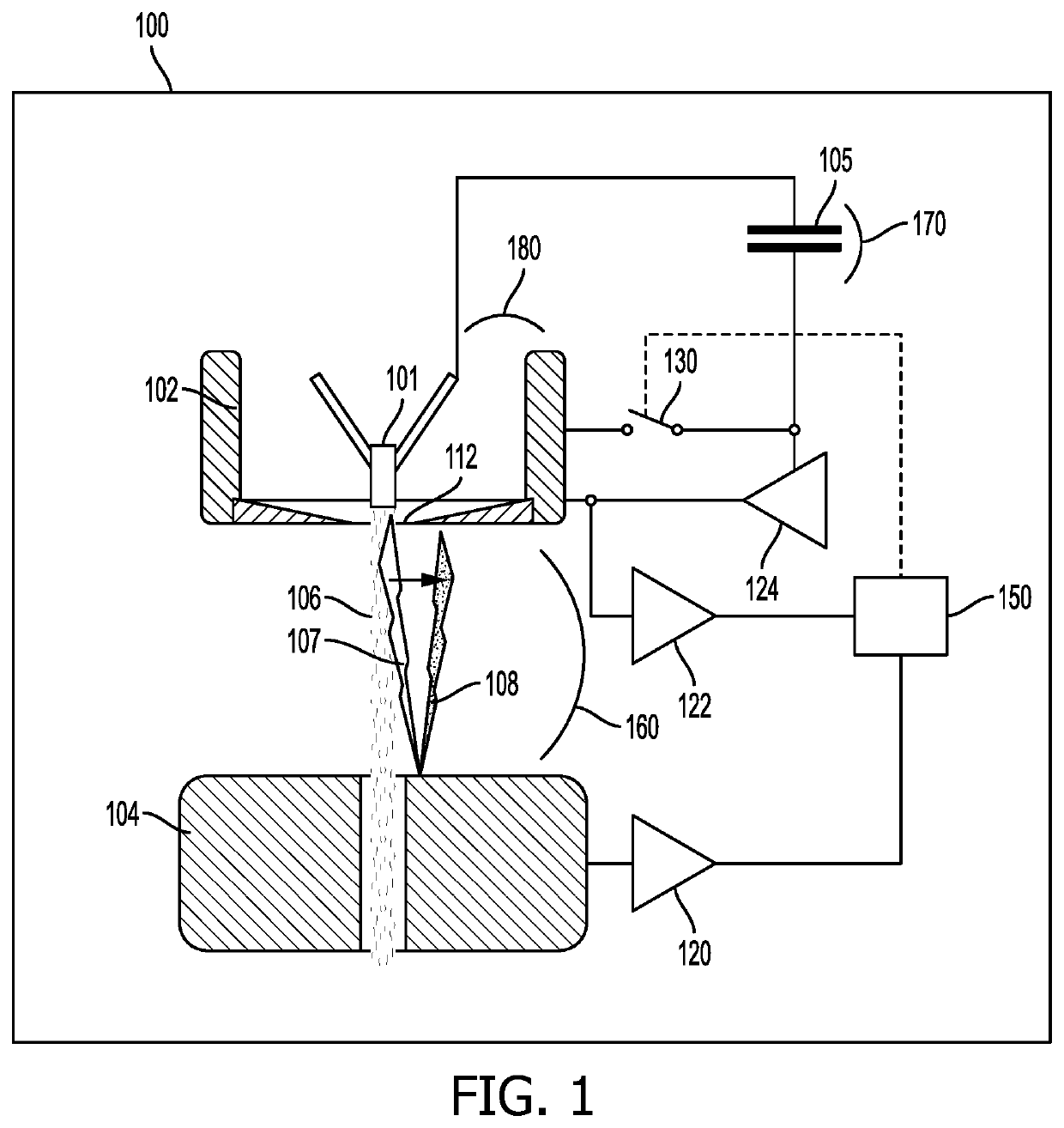
[0009]An exemplary and non-limiting advantage of various embodiments of the present invention is that the cathode and electronics connected to the cathode is protected from vacuum arc discharge currents which may greatly improve the reliability of the additive manufacturing process.
[0010]In various example embodiments of the present invention the low impedance negative voltage source may comprise a capacitor having a capacitance of a sufficient size so as to maintain a more negative potential to the grid compared to the cathode during a time duration of a vacuum arc discharge. An exemplary and non-limiting advantage of at least this embodiment is that it is simple and inexpensive to implement to make sure that the cathode elements or its electronics is not affected at any time during a vacuum discharge event.
[0013]An exemplary and non-limiting advantage of at least this example embodiment is that the cathode and electronics connected to the cathode is protected from vacuum arc discharge currents which may greatly improve the reliability of the additive manufacturing apparatus.

Problems solved by technology

One problem is that the cathode, as well as control electronics connected to the cathode is very sensitive to high discharge currents which may occur in an EBM machine.
The discharge currents may destroy the cathode element and / or the electronics connected to the cathode element, which in turn will stop the additive manufacturing process.

Method used


Image

  • Additive manufacturing of three-dimensional articles
  • Additive manufacturing of three-dimensional articles
  • Additive manufacturing of three-dimensional articles

Examples


Embodiment Construction

[0022]Various embodiments of the present invention will now be described more fully hereinafter with reference to the accompanying drawings, in which some, but not all embodiments of the invention are shown. Indeed, embodiments of the invention may be embodied in many different forms and should not be construed as limited to the embodiments set forth herein. Rather, these embodiments are provided so that this disclosure will satisfy applicable legal requirements. Unless otherwise defined, all technical and scientific terms used herein have the same meaning as commonly known and understood by one of ordinary skill in the art to which the invention relates. The term “or” is used herein in both the alternative and conjunctive sense, unless otherwise indicated. Like numbers refer to like elements throughout.

[0023]Still further, to facilitate the understanding of this invention, a number of terms are defined below. Terms defined herein have meanings as commonly understood by a person of ...


PUM

PropertyMeasurementUnit
negative voltageaaaaaaaaaa
accelerating voltageaaaaaaaaaa
pressureaaaaaaaaaa

Abstract

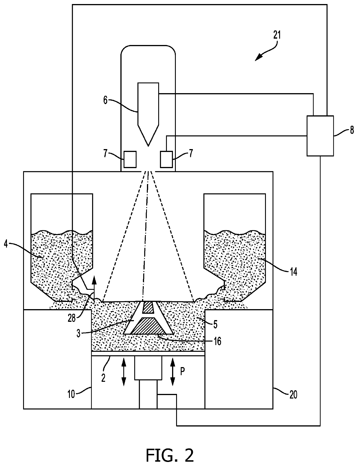
A method is provided for forming a three-dimensional article through successively depositing individual layers of powder material that are fused together so as to form the article. The method includes: providing at least one electron beam source emitting an electron beam; providing a leakage current detector for sensing a current through the anode and / or the Wehnelt cup; providing a low impedance voltage source connectable to the Wehnelt cup via a switch, where the voltage source is having a more negative potential than a negative potential applied to the cathode; and protecting the cathode against vacuum arc discharge energy currents when forming the three-dimensional article by providing the Wehnelt cup to the low impedance negative voltage by closing the switch when the leakage current detector is sensing a current through the anode and / or the Wehnelt cup which is higher than a predetermined value.

Description

CROSS-REFERENCE TO RELATED APPLICATIONS[0001]This application claims priority to and the benefit of U.S. Provisional Patent Application Ser. No. 62 / 437,119, filed Dec. 21, 2016, the contents of which as are hereby incorporated by reference in their entirety.BACKGROUNDRelated Field[0002]The present invention relates to a method for additive manufacturing of a three-dimensional articles by successively fusing individual layers of powder material.Description of Related Art[0003]Free-form fabrication or additive manufacturing is a method for forming three-dimensional articles through successive fusion of chosen parts of powder layers applied to a worktable.[0004]An additive manufacturing apparatus may comprise a work table on which the three-dimensional article is to be formed, a powder dispenser or powder distributor, arranged to lay down a thin layer of powder on the work table for the formation of a powder bed, a high energy beam for delivering energy to the powder whereby fusion of ...

Claims


Application Information

Patent Timeline
Patent Type & Authority Patents(United States)
IPC IPC(8): B23K15/00B23K15/02B28B1/00B28B17/00B29C64/268B33Y10/00B33Y50/02H01J37/302B22F3/105B22F7/06B23K15/06B29C64/153B29C64/264B33Y30/00H01J3/02H01J37/06H01J37/065H01J37/305H01J37/315
CPCB23K15/0086B22F3/1055B22F7/06B23K15/02B23K15/06B28B1/001B28B17/0081B29C64/153B29C64/264B29C64/268B33Y10/00B33Y30/00B33Y50/02H01J3/02H01J37/06H01J37/065H01J37/302H01J37/305H01J37/315H01J2237/0206H01J2237/3128Y02P10/25B22F12/41B22F10/28B22F12/45B22F10/364B22F10/36B22F10/362B22F12/55B22F10/32B22F12/90B22F10/00
Inventor EKBERG, CHRISTIAN
Owner ARCAM AB
Learn More