
Hybrid backup power supply system

a power supply system and hybrid technology, applied in the direction of emergency power supply arrangement, vehicle sub-unit features, battery/fuel cell control arrangement, etc., can solve the problems of only being able to use solid-state batteries, lithium ion batteries cannot discharge power, and conventional backup power supply systems are inadequate to meet the operating requirements of many vehicle ecus, etc., to achieve limit system size and cost, and the effect of sufficient life of the power supply system

Active Publication Date: 2021-02-16
BENDIX COMML VEHICLE SYST LLC
View PDF9 Cites 0 Cited by
  • Summary
  • Abstract
  • Description
  • Claims
  • Application Information

AI Technical Summary

Benefits of technology

This invention is about a system and method for providing power to an electrical load using a backup power supply. The system combines a supercapacitor and a battery to provide enough power for the load, while also keeping the system alive and minimizing its size and cost. This approach also makes it possible to handle inrush currents, which can be a challenge for some loads. Overall, this innovation offers an improved solution for ensuring reliable power supply in various situations.

Problems solved by technology

Conventional backup power supply systems, however, are inadequate to meet the operating requirements of many vehicle ECUs.
For example, lithium ion batteries are unable to discharge power at certain temperature extremes in which vehicles may operate and must be continuously recharged.
Solid state batteries can only be used a single time and are unable to provide sufficient power for the relatively high inrush currents in certain ECUs without employing a large number of the batteries.
Capacitors require a relatively long time to charge and are then quickly discharged when in use.

Method used


Image

  • Hybrid backup power supply system
  • Hybrid backup power supply system
  • Hybrid backup power supply system

Examples


Embodiment Construction

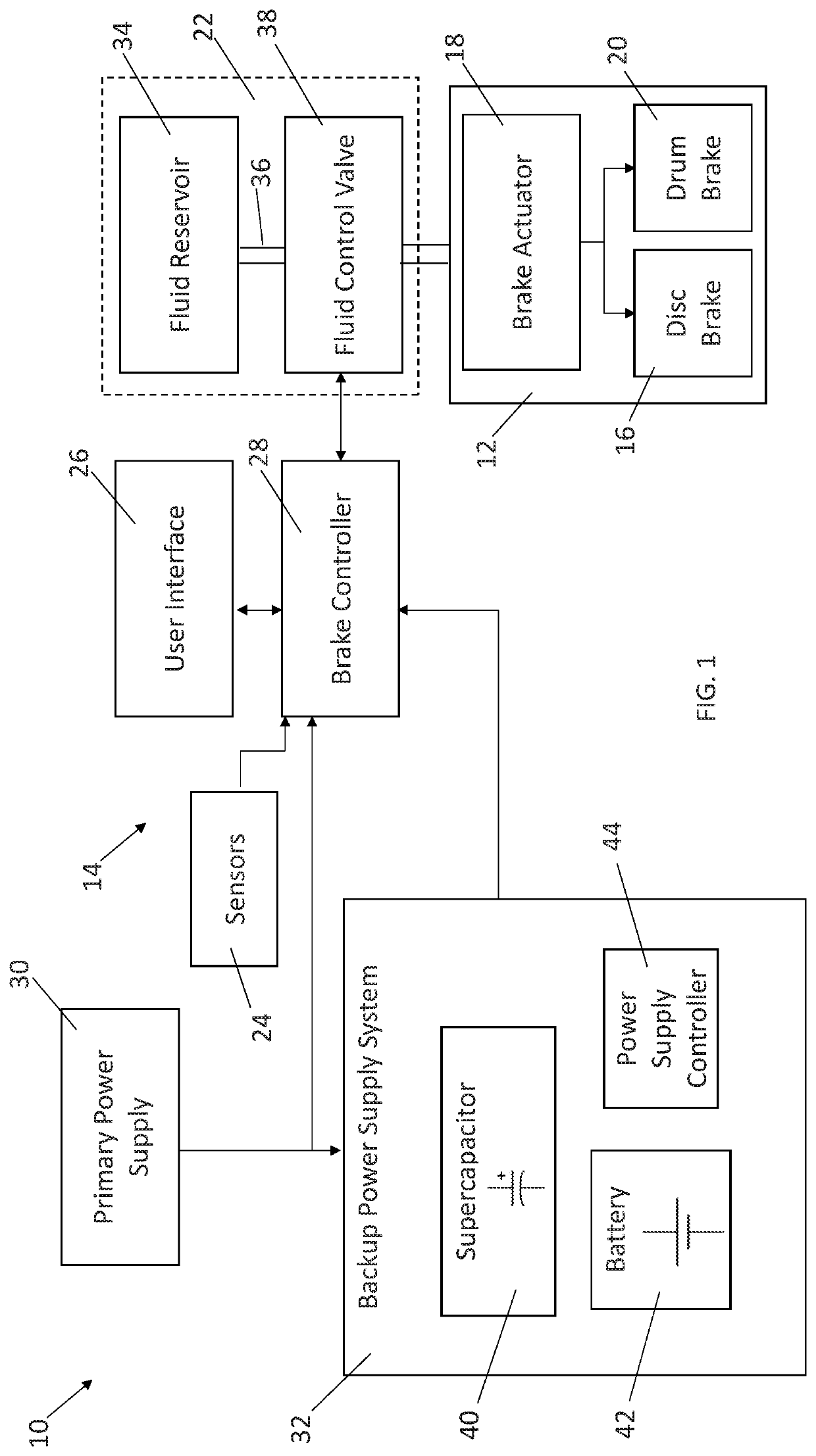
[0012]Referring now to the drawings wherein like reference numerals are used to identify identical components in the various views, FIG. 1 illustrates several components of a braking system 10 for a vehicle. In certain embodiments, the vehicle may comprise a heavy commercial vehicle and, in particular, a tractor-trailer (also referred to as a semi) containing a tractor or power unit and one or more trailers or towed units. It should be understood, however, that the inventions disclosed herein may find application in other types of commercial and non-commercial vehicles. It should also be understood that the inventions described herein may find application in a wide variety of vehicle systems other than braking system 10 including, but not limited to, powertrain systems, steering systems, fuel delivery systems, climate-control systems, etc. Finally, it should be understood that the particular application of the inventions disclosed herein (i.e. in a vehicle braking system) in exempla...


PUM


Abstract

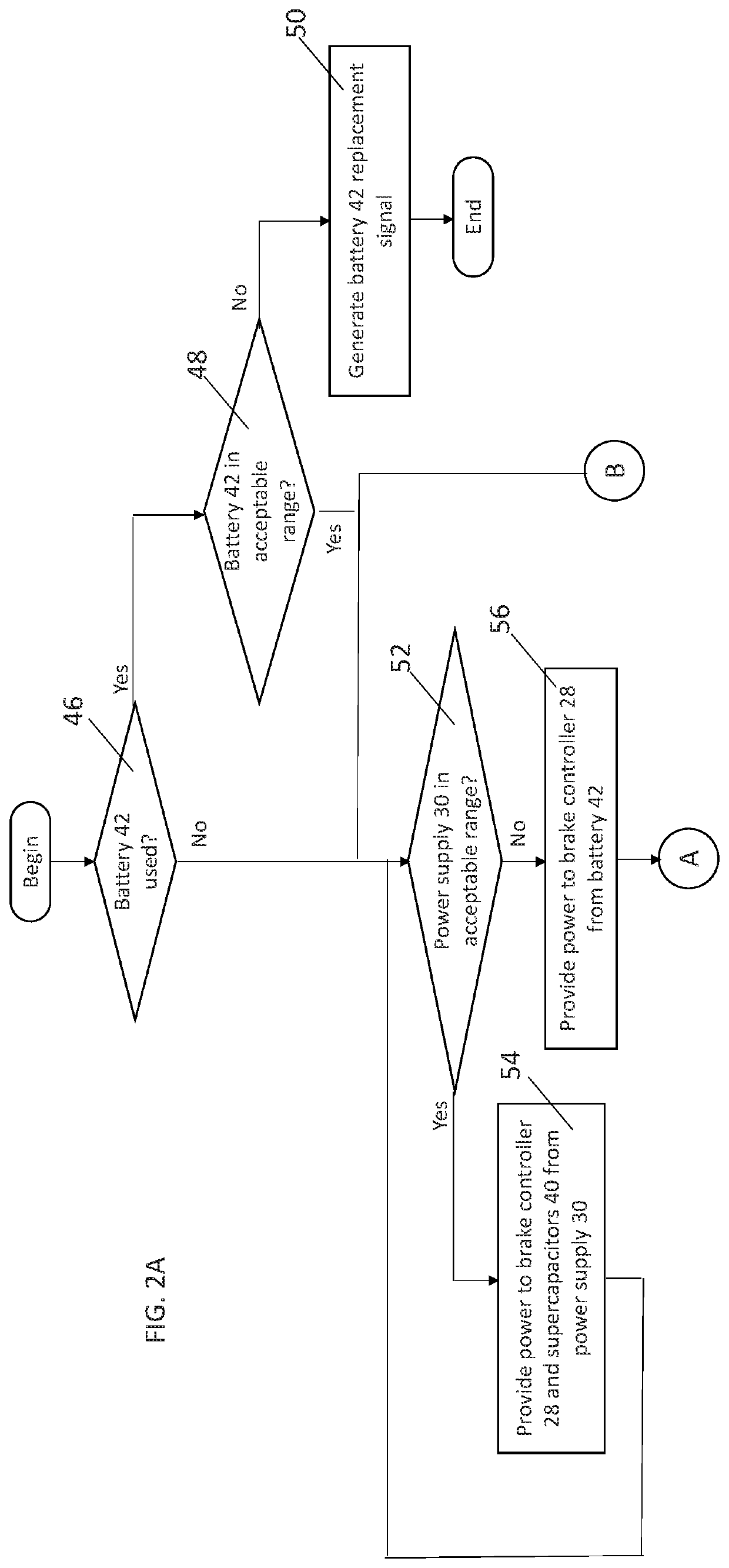
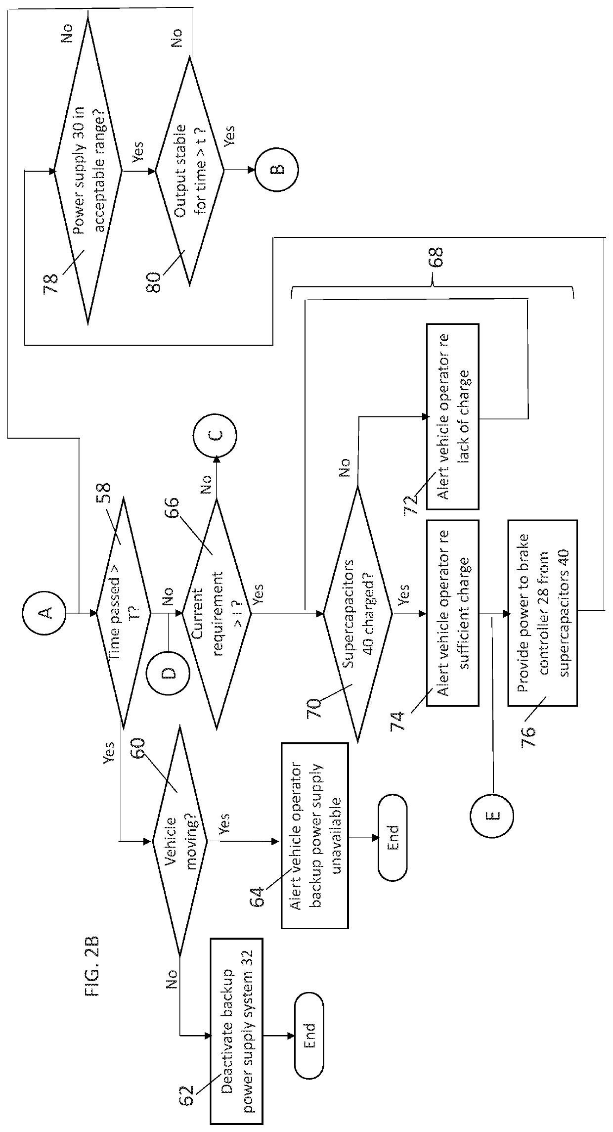
A backup power supply system and a method for providing power to an electrical load are provided. The system includes at least one supercapacitor, a battery and a power supply controller. The controller is configured to determine whether an output of a primary power supply for the load meets a first predetermined condition, determine, when the output of the primary power supply does not meet the first predetermined condition, a level of current required by the load, provide current to the load from the supercapacitor if the level of current required by the load meets a second predetermined condition, and, provide current to the load from the battery if the level of current required by the load does not meet the second predetermined condition until an output of the battery meets a third predetermined condition and thereafter provide current to the load from the supercapacitor.

Description

BACKGROUND OF THE INVENTIONa. Field of the Invention[0001]This invention relates to a backup power supply system for an electrical load. In particular, the invention relates to a backup power supply system and a method for providing power to an electrical load in which a supercapacitor and battery are controlled to provide power to the load in a manner that that supplies sufficient power for inrush currents, insures a sufficient life span of the power supply system, and limits system size and cost.b. Background Art[0002]Electrical systems in many applications are required to have backup power supplies. For example, certain vehicle systems such as braking and steering systems are critical to the safe operation of the vehicle. Electronic control units (ECUs) and other components for such safety-critical systems are expected to meet certain standards for functional safety such as those set forth in International Organization for Standards (ISO) Standard 26262 (“Road Vehicles—Functional...

Claims


Application Information

Patent Timeline
Patent Type & Authority Patents(United States)
IPC IPC(8): B60T8/17B60T17/22B60W10/26H02J7/34H02J9/06H02J7/00B60R16/033
CPCH02J9/061B60R16/033B60T17/22B60W10/26H02J7/0021B60T8/17B60Y2400/114H02J7/345H02J9/068B60L1/00B60L3/0076B60L3/0092B60L58/12B60L2200/28B60L2240/547B60L2240/549B60L2250/10B60L2270/20B60T7/20B60T13/662B60T2270/414H02J7/0047H02J2310/40Y02T10/70
Inventor CREMONA, MICHAEL D.HAYES, THOMAS J.DHAR, ABHINAV
Owner BENDIX COMML VEHICLE SYST LLC
Learn More