
Apparatus for in vivo dielectric spectroscopy

a dielectric spectroscopy and apparatus technology, applied in the field of sensors, can solve the problems of distorting the test, high loss in quality, quantity and economic sense, and limited techniques to in vitro or glass measuremen

Active Publication Date: 2021-02-16
HODGES JOHN W +1
View PDF23 Cites 0 Cited by
  • Summary
  • Abstract
  • Description
  • Claims
  • Application Information

AI Technical Summary

Benefits of technology

This approach allows for accurate, non-invasive, and real-time detection of biological process anomalies and characterization of nominal processes, facilitating preemptive actions and remedial assessments by minimizing the impact of the sensor on the organism and accounting for anisotropy, thus providing reliable in vivo measurements.

Problems solved by technology

These processes can be used, for example, in the detection of plant diseases which can greatly affect the total production of food and agricultural materials, and which could lead to high amount of losses in terms of quality, quantity and also in economic sense.
These techniques undesirably change the characteristics of the organism being measured so that the organism is altered in undesirable ways, distorting the test results.
However, these techniques are limited to in vitro, or in glass measurements.
Resonant techniques for dielectric spectroscopy, while highly accurate, require the subject to be entirely placed into an electrically resonant chamber which are completely impractical for living organisms so are not considered here.
These methods undesirably change the characteristics of the organism being measured so that the organism is altered in undesirable ways, distorting the test results.
These requirement make using the open-ended coaxial probe highly impractical for use in measuring in vivo processes.
However, for biological in vivo measurements the method is not practical because it requires large, flat, parallel-faced samples which is limited in biological subject by practical sample size to high frequencies in the microwave region.
Unlike open-ended coaxial probe and free space methods, transmission line method are destructive because the biological material must fill the fixture cross section of the transmission line sensor with no air gaps at fixture walls.
A second defect occurs in all of the conventional approaches described above at the interface between the open-ended coaxial probe or probe-like structure and the surface of the skin.
To date, despite tremendous effort, there is no generally acceptable electrical model of human skin.
Theses sensors provide information the can generally indicate an electrical response variation in the skin that can be taken into account, but given that there are multiple variable, computing an accurate response becomes very complex.
A third defect occurs in many of the solutions described above due to the fact that practical persistent data collection strategies to detect biological process anomalies, characterize nominal or steady state biological processes and identify novel biological processes to estimate the most probable state of the biological organism by observing it over time rather than ad hoc samples with great analytical precision is not possible due to in vivo subject's comfort.

Method used


Image

  • Apparatus for in vivo dielectric spectroscopy
  • Apparatus for in vivo dielectric spectroscopy
  • Apparatus for in vivo dielectric spectroscopy

Examples


Embodiment Construction

[0065]While the specification concludes with claims defining the features of the invention that are regarded as novel, it is believed that the invention will be better understood from a consideration of the following description in conjunction with the drawing figures, in which like reference numerals are carried forward. It is to be understood that the disclosed embodiments are merely exemplary of the invention, which can be embodied in various forms.

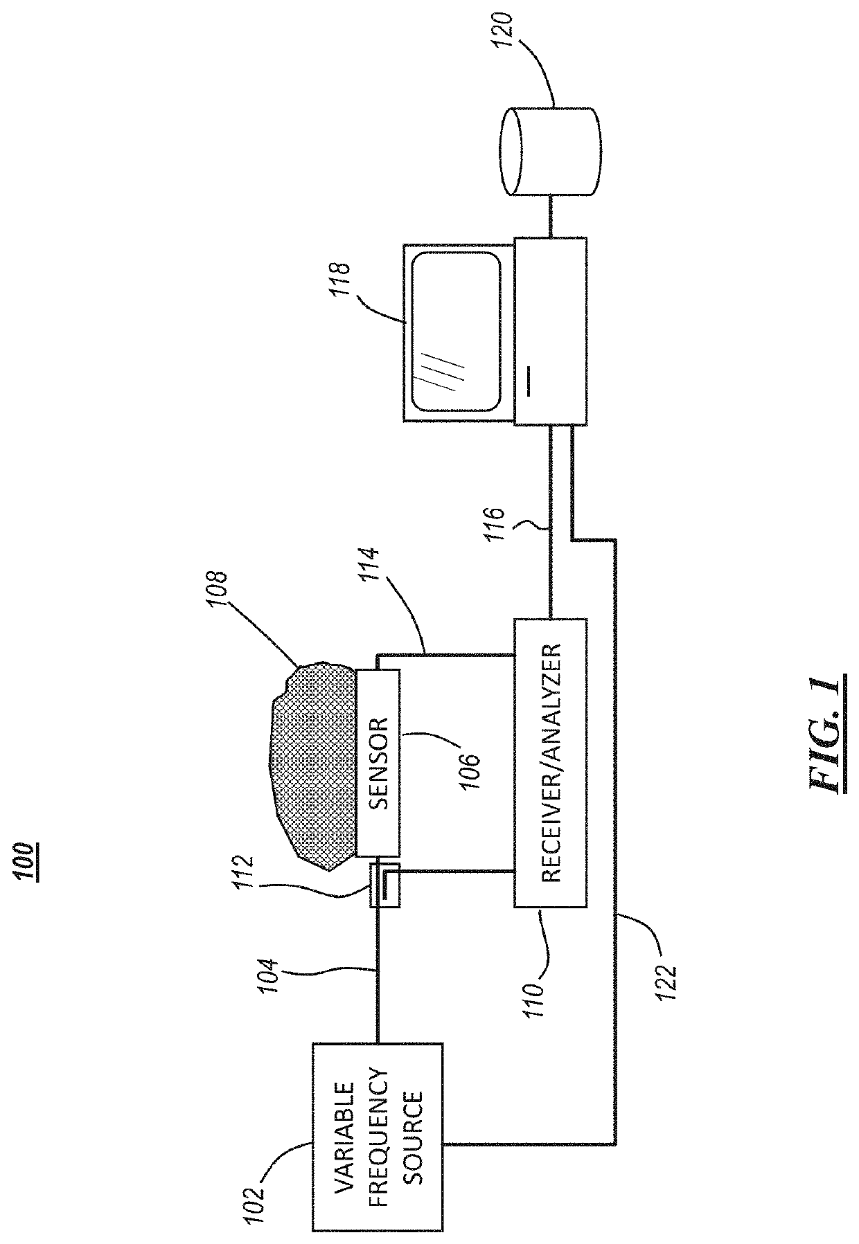
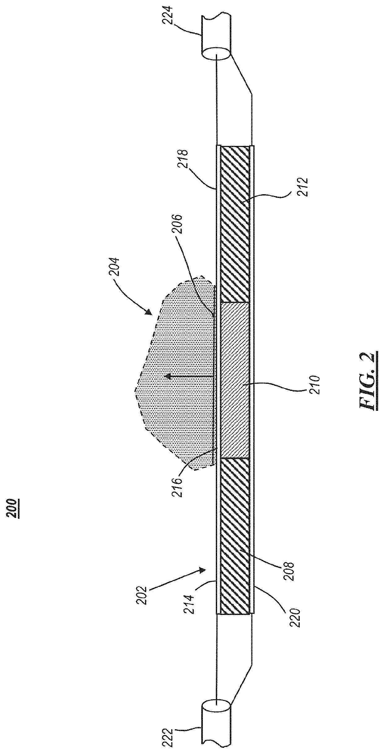
[0066]FIG. 1 is a block diagram of an in vivo dielectric spectroscopy system 100 using a sensor 106 having a composite dielectric construction, in accordance with some embodiments. The sensor is used to perform dielectric spectroscopy on a biological subject 108, which as shown here is a portion of a larger organism or other biological entity. Where the sensor 106 and the subject 108 meet there is an interface. For example, when the subject is an animal (or human), the sensor will be in contact with the subject's skin, which presents a...


PUM

PropertyMeasurementUnit
frequencyaaaaaaaaaa
frequenciesaaaaaaaaaa
frequencyaaaaaaaaaa

Abstract

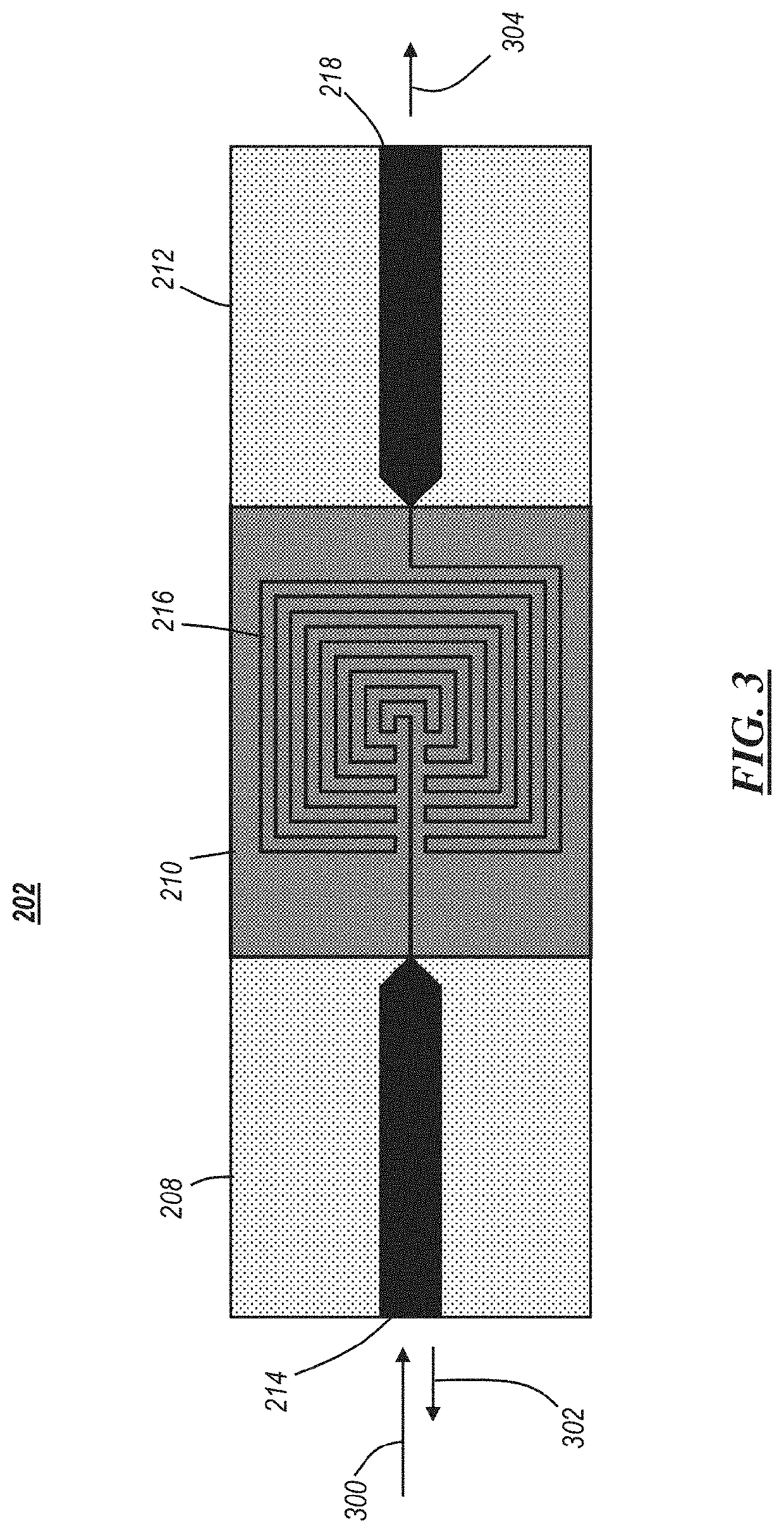
The apparatus includes a sensor having a multi-portion dielectric composite. A microstrip transmission line is formed on the dielectric composite and includes an input section, radiator portion, and an output section. The dielectric material adjacent the radiator portion is selected to substantially match that of the certain portions of a live organism being sensed, allowing other constituents of the organism to be sensed. This allow the radiator portion to effectively respond as if it were embedded inside the organism, removing substantial uncertainly from the measurement process. By then applying a plurality of signals to the sensor, the reflected and transmitted components of the signal can be measured and used to determine the amount of certain constituents are present in the organism.

Description

CROSS-REFERENCE TO RELATED APPLICATION[0001]This application claims priority to U.S. Provisional Patent Application No. 62 / 788,197 filed Jan. 4, 2019, the entirety of which is incorporated by reference.FIELD OF THE DISCLOSURE[0002]The present invention relates generally to sensors and related apparatuses for measuring biological properties of a living organism using an electric signal, and more particularly to using dielectric spectroscopy techniques to eliminate dielectric variability at the interface of a sensor and the living organism.BACKGROUND OF THE DISCLOSURE[0003]Variously known as swept frequency permittivity, resistive spectroscopy, impedance spectroscopy, or resistive pulse spectroscopy, the use of electromagnetic fields on the order of 1 Hz to tens of GHz to characterize the permittivity response of a biological sample over this broad range of frequencies, is more commonly referred to as dielectric spectroscopy. See H. Fricke, Philos. Mag. 14, 310 (1932), K. S. Cole and ...

Claims


Application Information

Patent Timeline
Patent Type & Authority Patents(United States)
IPC IPC(8): G01N27/02G01N27/22G01N33/487A61B5/0538
CPCG01N27/026A61B5/0538G01N27/028G01N27/221G01N33/48707A61B5/053A61B5/0507A61B2562/0228
Inventor HODGES, JOHN W.RIPPEN, MARC E.
Owner HODGES JOHN W
Learn More