Timing signal output device, and electronic apparatus
a timing signal and output device technology, applied in the direction of synchronisation arrangement, instruments, wireless communication, etc., can solve the problems of deteriorating precision of timing signals to be output, inability to accurately switch, etc., to reduce the deterioration of timing signals and improve vehicle characteristics
- Summary
- Abstract
- Description
- Claims
- Application Information
AI Technical Summary
Benefits of technology
Problems solved by technology
Method used
Image
Examples
first embodiment
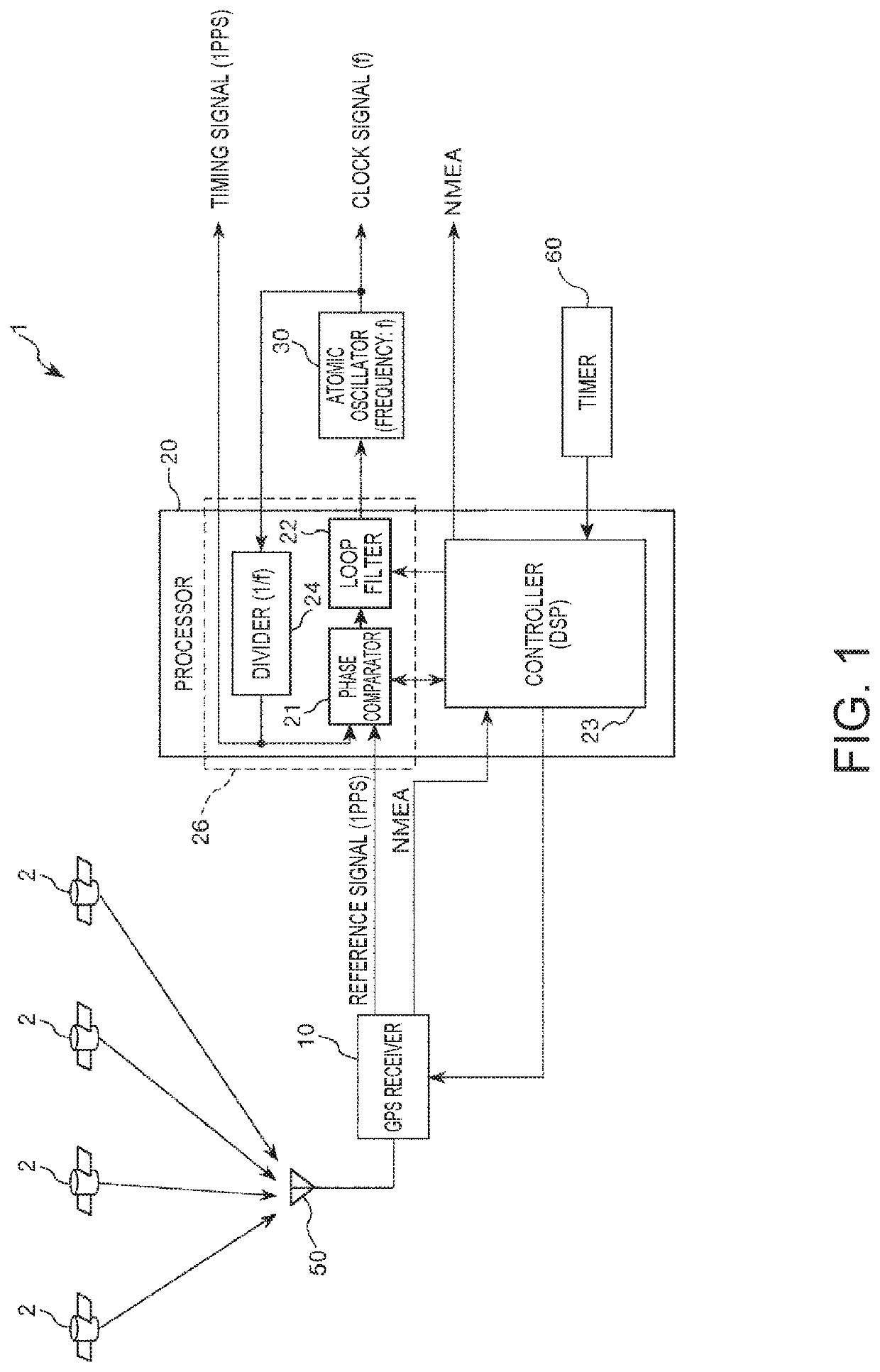
[0043]FIG. 1 is a diagram showing a schematic configuration example of a timing signal output device according to a first embodiment.
[0044]A timing signal output device 1 shown in FIG. 1 has a function of receiving satellite signals transmitted from GPS satellites 2 (an example of positioning satellites) and generating high-precision 1PPS as a timing signal. The timing signal output device 1 includes a GPS receiver 10 (a receiver), a processor 20, an atomic oscillator 30 (an oscillator), a GPS antenna 50, and a timer 60.
[0045]Note that a part or all of components of the timing signal output device 1 may be physically separated or may be integrated. For example, the GPS receiver 10 and the processor 20 may be respectively realized by separate ICs (Integrated Circuits) or may be realized as an IC of one chip.
[0046]The sections of the timing signal output device 1 are sequentially explained below.
[0047]The GPS receiver 10 (the receiver) has a function of performing various ...
second embodiment
[0083]FIG. 10 is a diagram showing a schematic configuration example of a timing signal output device according to a second embodiment.
[0084]This embodiment is the same as the first embodiment except that the switching of the first mode and the second mode is performed using statistical value information stored in a storage. Note that, in the following explanation, concerning the second embodiment, differences from the first embodiment are mainly explained. Explanation of similarities to the first embodiment is omitted. In FIG. 10, the same components as the components in the first embodiment are denoted by the same reference numerals and signs.
[0085]A timing signal generating device 1A shown in FIG. 10 includes the GPS receiver 10 (a receiver), a processor 20A, the atomic oscillator 30 (an oscillator), a storage 40, the GPS antenna 50, and the timer 60.
[0086]The processor 20A includes the phase comparator 21, the loop filter 22, a controller 23A, and the divider 24. The controller ...
third embodiment
[0094]FIG. 11 is a diagram showing a schematic configuration example of a timing signal output device according to a third embodiment.
[0095]This embodiment is the same as the first embodiment except that statistical value information is calculated using information stored in a storage and the switching of the first mode and the second mode is performed using a result of the calculation. Note that, in the following explanation, concerning the third embodiment, differences from the embodiments explained above are mainly explained. Explanation of similarities to the embodiments explained above is omitted. In FIG. 11, the same components as the components in the embodiments explained above are denoted by the same reference numerals and signs.
[0096]A timing signal generating device 1B shown in FIG. 11 includes the GPS receiver 10 (a receiver), a processor 20B, the atomic oscillator 30 (an oscillator), a storage 40B, the GPS antenna 50, and the timer 60.
[0097]The processor 20B includes th...
PUM
 Abstract
Description
Claims
Application Information
 - Generate Ideas
- Intellectual Property
- Life Sciences
- Materials
- Tech Scout
- Unparalleled Data Quality
- Higher Quality Content
- 60% Fewer Hallucinations
Browse by: Latest US Patents, China's latest patents, Technical Efficacy Thesaurus, Application Domain, Technology Topic, Popular Technical Reports.
© 2025 PatSnap. All rights reserved.Legal|Privacy policy|Modern Slavery Act Transparency Statement|Sitemap|About US| Contact US: help@patsnap.com


