Stokes parameter measurement device and method
a measurement device and stokes technology, applied in measurement devices, optical radiation measurement, instruments, etc., can solve the problems of difficult high-precision measurement of stokes parameters, and achieve the effect of suppressing polarization fluctuations and pdl
- Summary
- Abstract
- Description
- Claims
- Application Information
AI Technical Summary
Benefits of technology
Problems solved by technology
Method used
Image
Examples
first embodiment
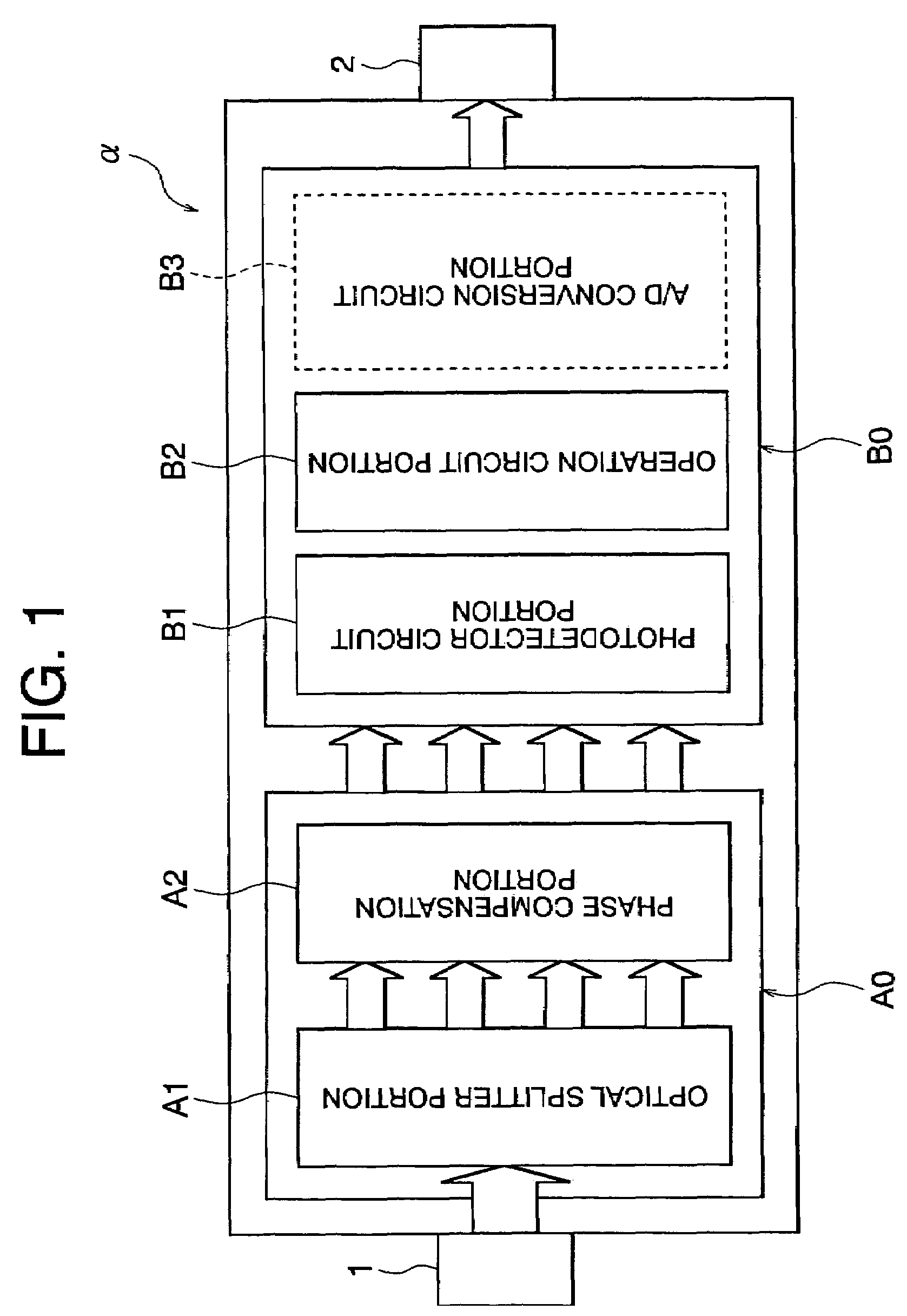
[0046]FIG. 1 is a block diagram showing the configuration of the Stokes parameter measurement device of a first embodiment.
[0047]The Stokes parameter measurement device a of this example comprises an input portion 1, which is an incidence portion comprising a receptacle, collimating lens or similar; a polarization analyzer optical portion A0; an electrical circuit portion B0; an output portion 2 comprising a GP-IB or other. The polarization analyzer optical portion A0 comprises an optical splitter portion A1 and a phase compensation portion A2; the electrical circuit portion B0 comprises a photodetector circuit portion B1, employing a photodiode or similar and an operation circuit portion B2. Note that, if necessary the electrical circuit portion B0 comprises the A / D conversion circuit portion B3 and / or the analog output circuit portion (not shown).
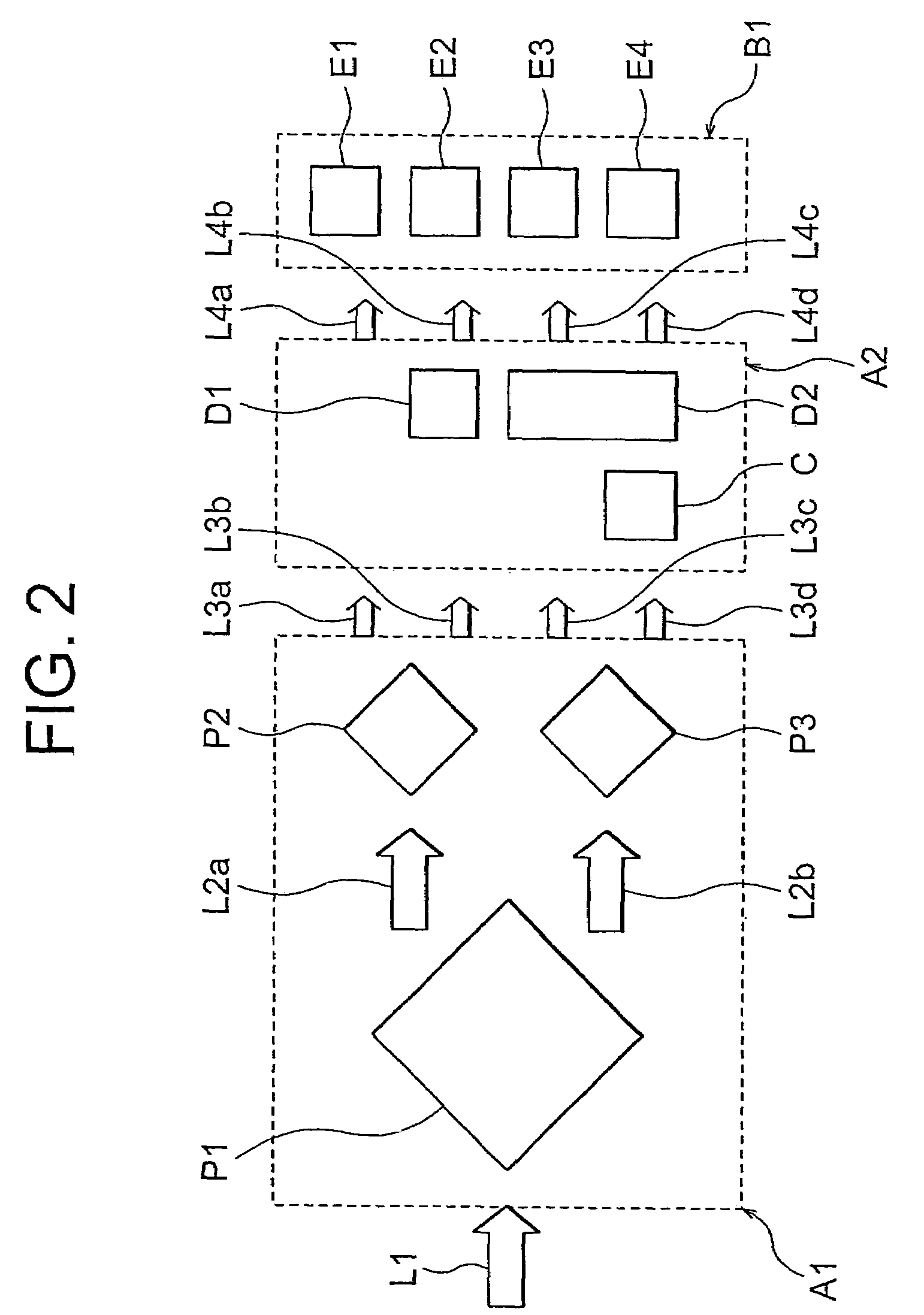
[0048]FIG. 2 shows one example of the configuration of the optical splitter portion A1, phase compensation portion A2, and photodetector...
second embodiment
[0073]Below, the Stokes parameter measurement device of a second embodiment is explained. In the measurement device of the second embodiment, lenses to adjust the beam size are added to the polarization analyzer optical portion A0 shown in FIG. 2.
[0074]FIG. 6 shows a portion of the optical splitter portion A1 in the measurement device of the second embodiment. As is clear from the figure, in the optical splitter portion A1, a beam expander lens 51 to enlarge the beam diameter of the incident light ray L1 and a collimator lens 52 to cause the incident light ray L1 with enlarged beam diameter to be collimated before incidence on the prism P1 are positioned sequentially as a stage preceding the prism P1.
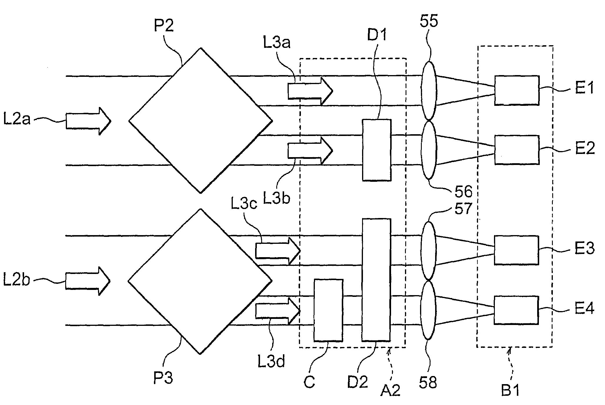
[0075]FIG. 7 shows an example in which condensing lenses 55, 56, 57, 58 are placed between the photodetector circuit portion B1 and the phase compensation portion A2. Here, after the second split light rays L3a, L3b, L3c, L3d have passed through the phase compensation portion A2, prior ...
third embodiment
[0076]Below, the Stokes parameter measurement device of a third embodiment is explained. In the measurement device of the third embodiment, the optical splitter portion A1 of FIG. 2 comprises a single prism.
[0077]In FIG. 8A is a perspective view of the prism PQ comprised by the optical splitter portion A1, and FIG. 8B is a side view of the prism PQ. In the optical splitter portion A1, the light-receiving portion of the prism PQ is a quadrangular-pyramid shape. The incident light L1 from the input portion 1 shown in FIG. 1 is incident on the apex portion 61 of this pyramid shape, that is, on the four side faces 62 to 65 containing four edges; as a result, a single prism PQ can split the incident light L1 into four split light rays L3a to L3d in a single operation. Hence the configuration of the optical splitter portion A1 can be simplified.
[0078]In FIG. 9A shows a variation of the prism PQ of FIG. 8A and 8B. In this case, the incidence side and the emission side of the prism PQ both ...
PUM
 Abstract
Description
Claims
Application Information
 - R&D
- Intellectual Property
- Life Sciences
- Materials
- Tech Scout
- Unparalleled Data Quality
- Higher Quality Content
- 60% Fewer Hallucinations
Browse by: Latest US Patents, China's latest patents, Technical Efficacy Thesaurus, Application Domain, Technology Topic, Popular Technical Reports.
© 2025 PatSnap. All rights reserved.Legal|Privacy policy|Modern Slavery Act Transparency Statement|Sitemap|About US| Contact US: help@patsnap.com


