
Sheet transporting mechanism and image formation apparatus comprising the same

a transport mechanism and a technology of an image formation apparatus, applied in the directions of transportation and packaging, thin material handling, article delivery, etc., can solve the problems of low productivity, increased cost, and difficulty in assembling one-way clutches separately, so as to achieve low productivity, increase cost, and improve precision

Active Publication Date: 2019-09-17
KONICA MINOLTA TECH DEV WUXI
View PDF9 Cites 0 Cited by
  • Summary
  • Abstract
  • Description
  • Claims
  • Application Information

AI Technical Summary

Benefits of technology

[0007]The configuration disclosed in U.S. Patent Publication No. 2012 / 0032388 requires driving by a double pulse signal, resulting in relatively low productivity. Moreover, because of a characteristic of the one-way clutch, precision also deteriorates. Furthermore, separately installing the one-way clutches invites increased cost.
[0009]One or more embodiments of the present invention provide a sheet transporting mechanism capable of reducing cost while also increasing productivity and an image formation apparatus comprising the same.

Problems solved by technology

The configuration disclosed in U.S. Patent Publication No. 2012 / 0032388 requires driving by a double pulse signal, resulting in relatively low productivity.
Moreover, because of a characteristic of the one-way clutch, precision also deteriorates.
Furthermore, separately installing the one-way clutches invites increased cost.
The configuration of Japanese Laid-Open Patent Publication No. 2015-020822 requires precisely controlling the operation of each mechanism, and accordingly, it must select an expensive stepping motor, which results in significantly increased cost.
Furthermore, a gripper reciprocates over a sheet passage plane, and accordingly, productivity is decreased.

Method used


Image

  • Sheet transporting mechanism and image formation apparatus comprising the same
  • Sheet transporting mechanism and image formation apparatus comprising the same
  • Sheet transporting mechanism and image formation apparatus comprising the same

Examples


Embodiment Construction

[0025]Hereinafter, embodiments of the present invention will be described with reference to the drawings. However, the scope of the invention is not limited to the disclosed embodiments.

[0026]Hereinafter, with reference to the drawings, embodiments of the present invention will now be described in detail. Those skilled in the art can implement various alternative embodiments based on suggestions from these embodiments, and the present invention is not limited to the embodiments described herein. For convenience for understanding the present invention, some figures do not indicate reference characters indicated in other figures.

[0027]A sheet transporting mechanism according to one or more embodiments of the present invention is applied to an image formation system or the like, and specifically, it is applied to a sheet binding mechanism that binds sheets which have images formed thereon and are subsequently accumulated.

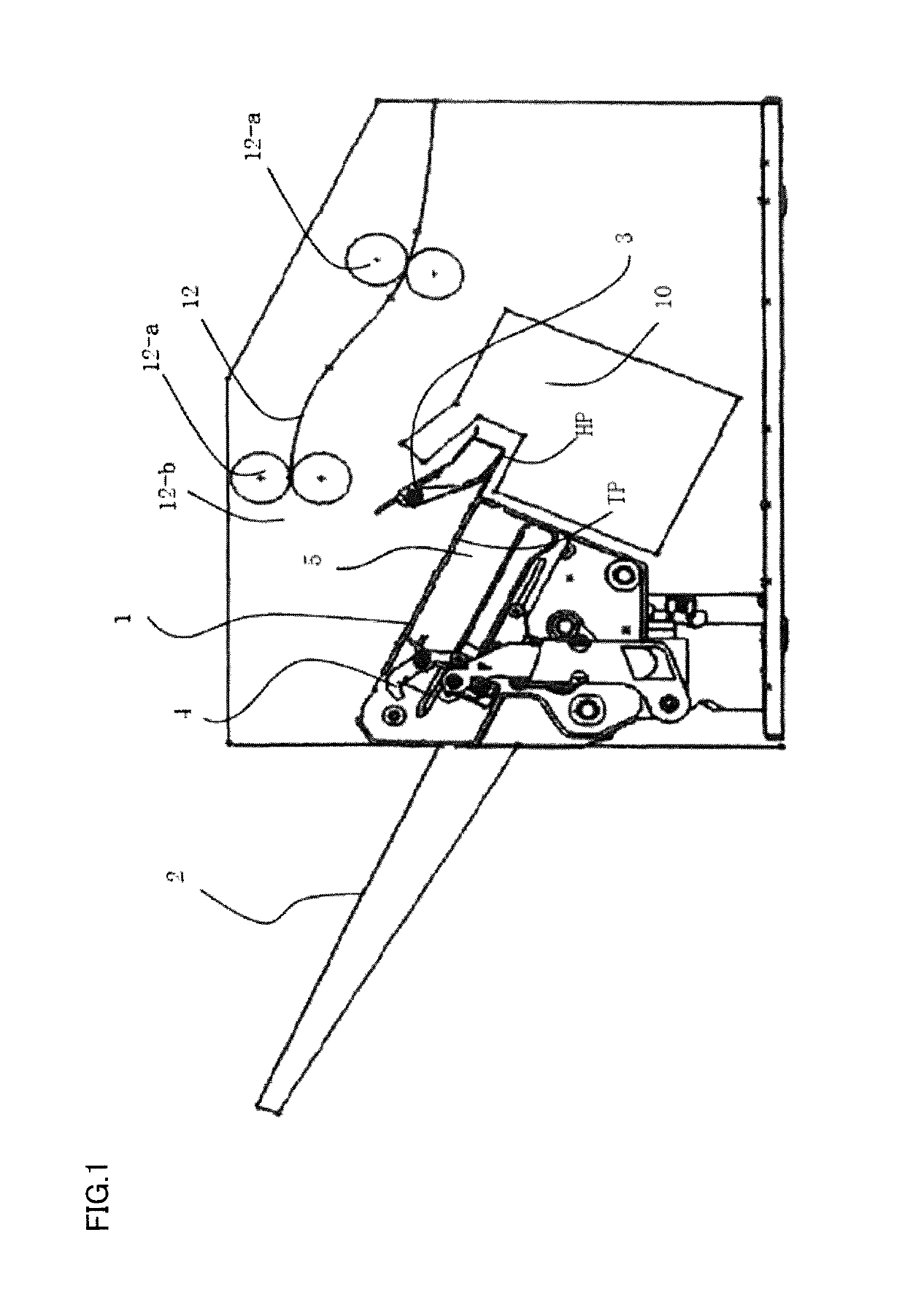
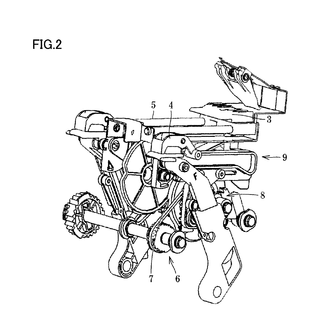
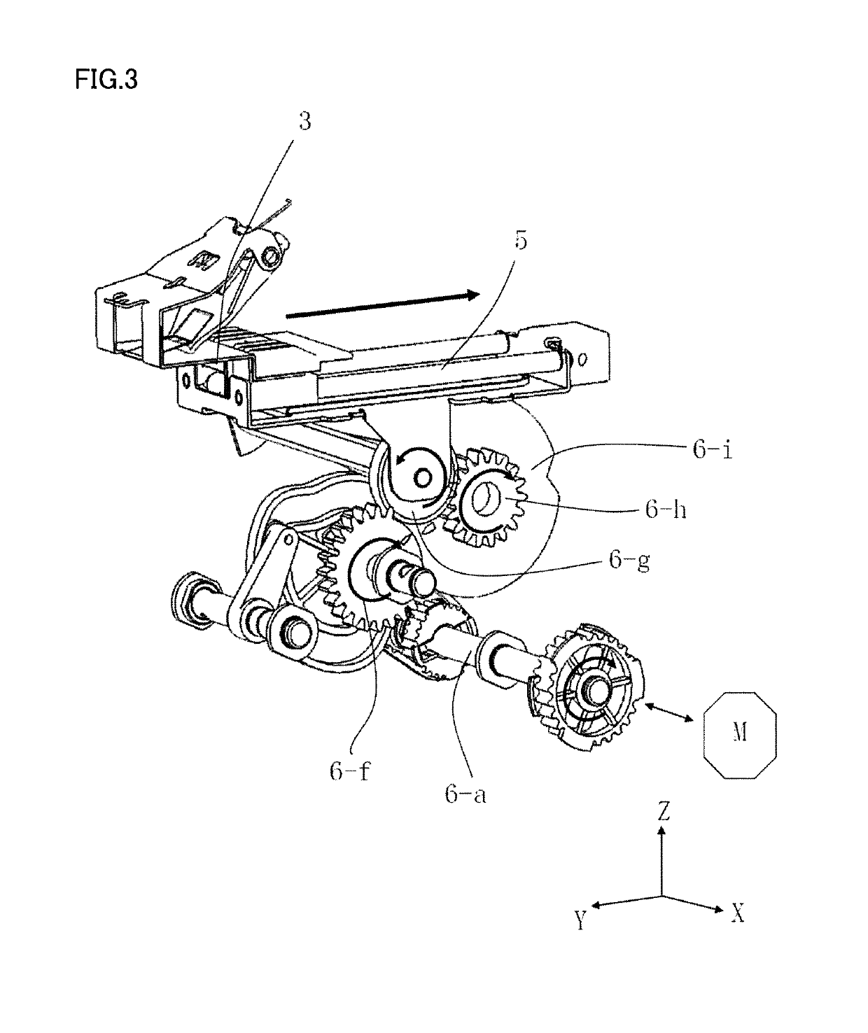
[0028]FIG. 1 is a schematic diagram showing a local part of an im...


PUM

PropertyMeasurementUnit
sheet transportingaaaaaaaaaa
driving forceaaaaaaaaaa
circumferenceaaaaaaaaaa

Abstract

A sheet transporting mechanism transports a sheet from a storage tray to a stacking tray, and includes: a first transporter that moves between initial and first positions to transport the sheet from the initial position toward the stacking tray; a second transporter that transports the transported sheet by the first transporter to the stacking tray; a single motor that drives the first and second transporters; a guide rail that guides movement of the second transporter; a first transmission gear that transmits a driving force of the single motor to move the first transporter between the initial and first positions; a second transmission gear that transmits the driving force of the single motor to move the guide rail in an upward and downward direction; and a third transmission gear that transmits the driving force of the single motor to allow the second transporter to be guided by the guide rail.

Description

CROSS-REFERENCE TO RELATED APPLICATIONS[0001]Chinese Patent Application No. 201710532764.9 filed on Jul. 3, 2017, including description, claims, drawings, and abstract the entire disclosure is incorporated herein by reference in its entirety.BACKGROUNDTechnical Field[0002]The present invention relates to a sheet transporting mechanism and an image formation apparatus comprising the same.Description of the Related Art[0003]For example, U.S. Patent Publication No. 2012 / 0032388 and Japanese Laid-Open Patent Publication No. 2015-020822 disclose an image formation apparatus having a sheet transporting mechanism in which it is necessary that sheets having images formed thereon are fed out by a sheet feeding system and accumulated in a storage tray and the accumulated sheets are bound by a sheet binding means and then transported in a transporting direction and thus discharged to a stack tray located downstream of the transporting direction, as conventional.[0004]U.S. Patent Publication No...

Claims


Application Information

Patent Timeline
Patent Type & Authority Patents(United States)
IPC IPC(8): B65H29/46B65H29/00B65H31/30
CPCB65H29/46B65H31/3081B65H29/003B65H31/3045B65H2301/4471B65H2403/51B65H5/062B65H5/10B65H31/02B65H2301/4212B65H2301/4213B65H2405/11151B65H2405/5812B65H2405/5831B65H2801/27
Inventor XU, JIANGTAOHU, JIE
Owner KONICA MINOLTA TECH DEV WUXI
Learn More