
Rotation detection device

a detection device and rotation technology, applied in the direction of machines/engines, electrical control, instruments, etc., can solve the problems of deteriorating precision of output signals corresponding to length centers of teeth of rotors, difficult to expand the detectable gap of the rotation detection device etc., to achieve the expansion of the detectable gap relative to the rotor, the effect of maximizing the signal amplitude and the sub signal

Active Publication Date: 2020-08-18
DENSO CORP
View PDF14 Cites 0 Cited by
  • Summary
  • Abstract
  • Description
  • Claims
  • Application Information

AI Technical Summary

Benefits of technology

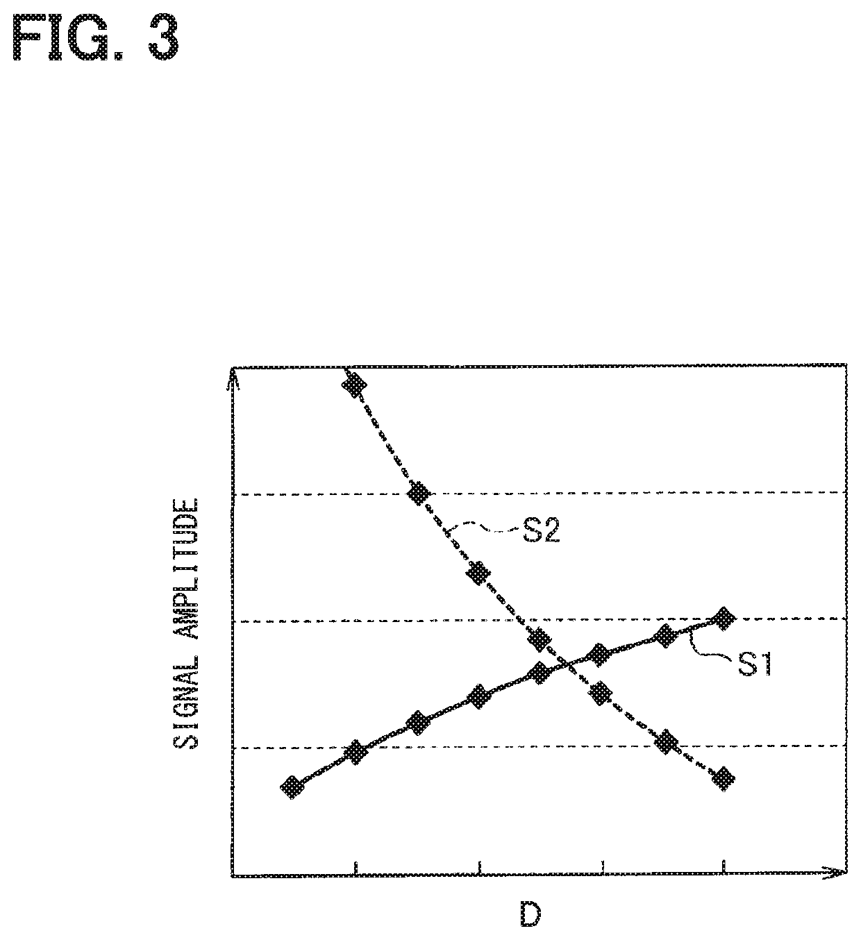
The present invention relates to a rotation detection device that can increase the detectable gap between the device and the rotor by arranging each of the magnetoresistive element pairs to maximize both signal amplitudes of the main and sub signals. This ensures that the signal amplitudes of the main and sub signals are not reduced even when the gap between the device and the rotor becomes larger, thereby expanding the detectable gap between the rotor and the device.

Problems solved by technology

Thus, since signal amplitudes of the first differential signal and the second differential signal become smaller, it is possible that a precision of an output signal corresponding to length centers of the teeth of the rotor is deteriorated.
Since the signal amplitudes of the first differential signal and the second differential signal are limited, it is difficult to expand a detectable gap of the rotation detection device relative to the rotor.

Method used


Image

  • Rotation detection device
  • Rotation detection device
  • Rotation detection device

Examples


first embodiment

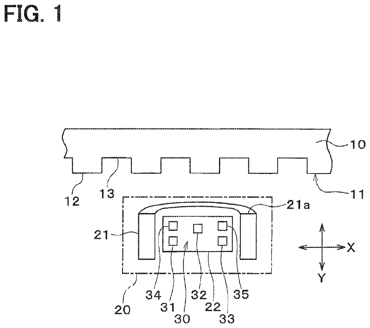
[0021]Hereinafter, a first embodiment of the present disclosure will be described with reference to the drawings. A rotation detection device according to the present disclosure, for example, is used as a crank angle detection device of an internal combustion engine. As shown in FIG. 1, the rotation detection device 20 is located to face an outer peripheral part 11 of a rotor 10 of a gear type. The rotor 10 is fixed to a crank shaft of an engine that is the internal combustion engine. The outer peripheral part 11 of the rotor 10 includes a protrusion part 12 and a recession part 13 which are alternately arranged in a rotation direction of the rotor 10. As shown in FIG. 1, a part of the outer peripheral part 11 of the rotor 10 is linearly expanded.

[0022]The rotation detection device 20 is configured to detect a rotation state of the rotor 10. The rotation detection device 20 includes a bias magnet 21 that is a cylindrical shape, and a sensor chip 22 that is located at a position that...


PUM


Abstract

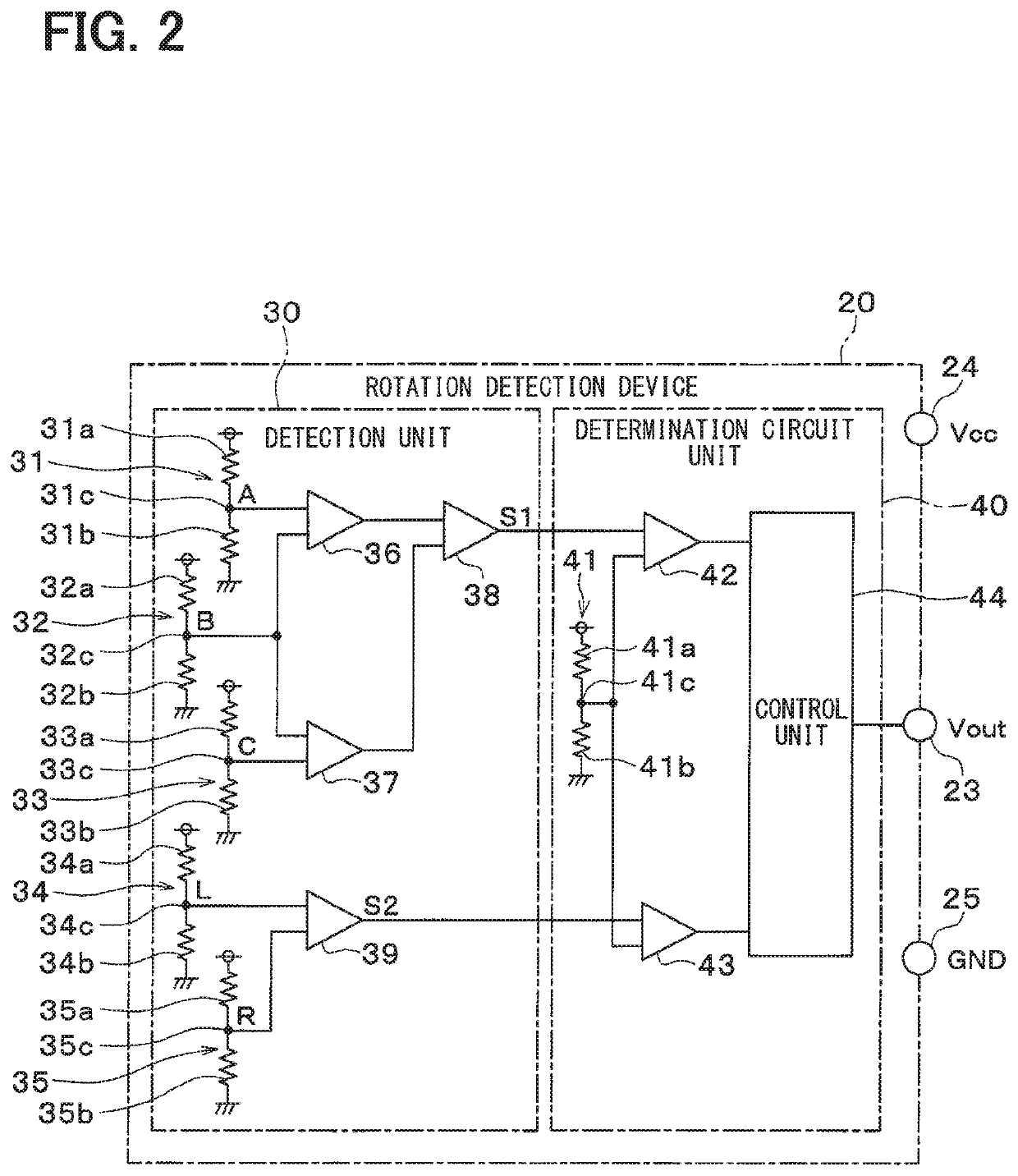
A rotation detection device includes a detection unit and a determination circuit unit. A first magnetoresistive element pair, a second magnetoresistive element pair and a third magnetoresistive element pair are located to be farther from the end part than a fourth magnetoresistive element pair and a fifth magnetoresistive element pair are. The second magnetoresistive element pair is located in a region surrounded by the first magnetoresistive element pair, the third magnetoresistive element pair, the fourth magnetoresistive element pair and the fifth magnetoresistive element pair. The detection unit is to generate a main signal based on outputs of the first magnetoresistive element pair, the second magnetoresistive element pair and the third magnetoresistive element pair and to generate a sub signal based on outputs of the fourth magnetoresistive element pair and the fifth magnetoresistive element pair.

Description

CROSS REFERENCE TO RELATED APPLICATIONS[0001]The present disclosure relates to a rotation detection device which detects a rotation state of a rotor. This application is a U.S. national phase of International Application No. PCT / JP2016 / 070765 filed on Jul. 14, 2016, the disclosure of which is incorporated herein by reference.TECHNICAL FIELDBackground Art[0002]Conventionally, a rotation detection device configured to detect a rotation state of a rotor, for example, is disclosed in Patent Literature 1. Specifically, the rotation detection device includes a sensor chip where plural magnetoresistive elements are provided, a bias magnet that applies a bias magnetic field to each of the magnetoresistive elements, and a processing circuit that executes a signal processing based on an output of each of the magnetoresistive elements. Each of the magnetoresistive elements is located at a position facing the rotor. The magnetoresistive elements constitute plural magnetoresistive element pairs ...

Claims


Application Information

Patent Timeline
Patent Type & Authority Patents(United States)
IPC IPC(8): G01R33/09G01D5/245G01P3/488G01P13/04F02D41/00G01D5/16
CPCG01R33/09G01D5/16G01D5/2451G01D5/245F02D41/009G01P13/04G01P3/488G01R33/091G01D2205/85
Inventor KOBAYASHI, ATSUSHIMAKITA, MICHIHIRO
Owner DENSO CORP
Learn More