
Foam reefer wall backing with spaced rows of loops for better adhesion

a technology of reefer wall and loop, which is applied in the direction of packaging, railway components, synthetic resin layered products, etc., can solve the problems of inherently increasing the bonding capability of the scrim surface, limiting the success of various methods to enhance the bond, and too broad encompassing, so as to achieve less potential downtime, greater adhesion, and less thermal efficiency loss

Active Publication Date: 2020-12-22
LAROCCO MICHAEL C
View PDF1 Cites 0 Cited by
  • Summary
  • Abstract
  • Description
  • Claims
  • Application Information

AI Technical Summary

Benefits of technology

The patent describes a method to improve the insulation of storage units by using glass-reinforced thermoplastic interior wall panels. These panels provide better adhesion and reduce the risk of damage during packaging and transportation. As a result, the units have a longer lifespan and lower repair and replacement costs.

Problems solved by technology

Although the idea was novel and relevant, it was later found to be too broad encompassing “any” panel rather than just panels used for the interiors of refrigerated trailers, truck bodies, container, and rail cars.
Additionally, various methods to enhance this bond have been limited in their success.
For example, lofting the scrim (creating a brush to break surface fibers loose to create better bonding) or using other materials / films to help chemically bond foam to panel do not inherently increase the bonding capability of the scrim surface.
Fork trucks and other freight loading mechanisms create tremendous pressure and damage to the inside of a refrigerated unit resulting pressure against the wall as cargo gets stacked in such units.
The result is wall delamination from the foam structure and a wall that now is compromised.
The scrim helps to grab the foam but methods to scrape or loft scrim, use of films, and other methods of bonding foam have not eliminated the problem.
When the wall delaminates from the foam, it allows moisture to infiltrate, resulting in potential damage and ultimate costly repair or replacement of the interior wall.

Method used


Image

  • Foam reefer wall backing with spaced rows of loops for better adhesion
  • Foam reefer wall backing with spaced rows of loops for better adhesion
  • Foam reefer wall backing with spaced rows of loops for better adhesion

Examples


first embodiment

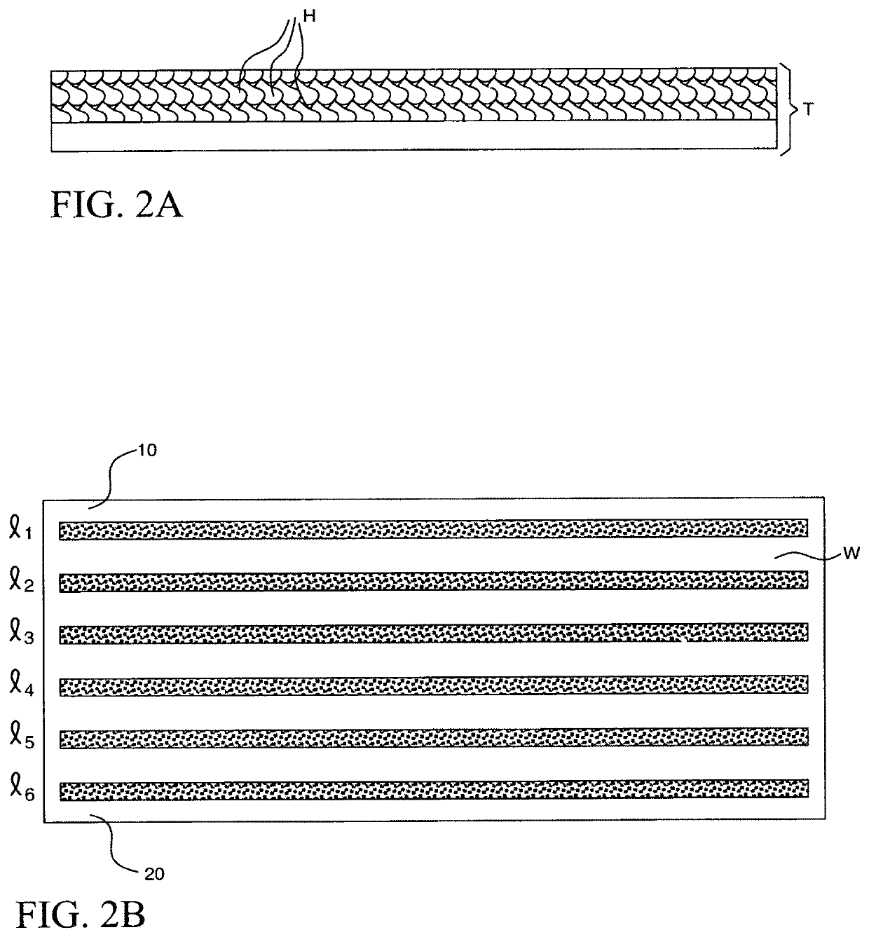
[0050]FIG. 2B is a drawing showing improved reefer wall W with a plurality of lateral hook tape sections (l1 through l6) applied in a spaced, horizontal arrangement from near the top 10 to near the bottom 20 of wall W prior to the application of foam thereto;

second embodiment

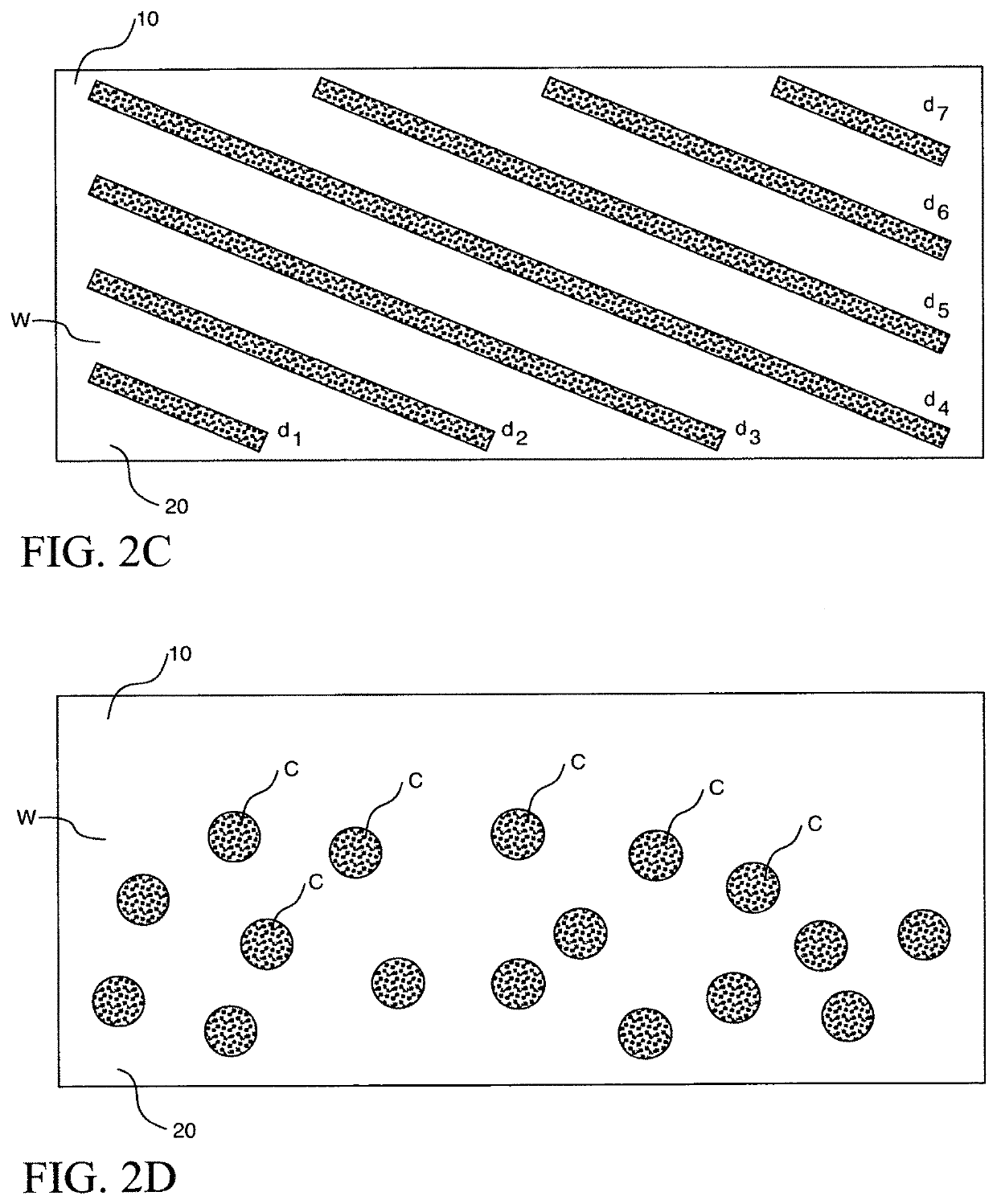
[0051]FIG. 2C is a drawing showing improved reefer wall W with a plurality of hook tape sections (d1 through d7) applied in a spaced, diagonal arrangement from left to right, from near the top 10 to near the bottom 20 of wall W prior to the application of foam thereto; and

[0052]FIG. 2D is a drawing showing a third, representative embodiment of improved reefer wall W with a plurality of circular-shaped hook tape sections c applied randomly to just a lower section 20 of wall W (in a typically more vulnerable region for delamination or loading damage) prior to the application of foam thereto. These are but three such arrangements, it being understood that still other arrangements of full hook tape, various subsections of hook material (in rectangles, squares, triangles, etc.) may be randomly or purposefully placed about in an orderly pattern prior to “foaming”. To a lesser degree, the looped “partner” to such hook sections may be situated about, in place of (i.e., in the alternative) O...


PUM

PropertyMeasurementUnit
sizeaaaaaaaaaa
sizeaaaaaaaaaa
heightsaaaaaaaaaa

Abstract

An improved reefer wall panel having better foam adhesion includes purposefully spaced gaps in the looped sections to be foamed. Such spaced gaps may extend horizontally, vertically, diagonally or in combinations of directions. These gaps (random or patterned) may be applied to the whole of a reefer panel or to just the more vulnerable lower sections where traffic impact during loading / unloading is more common and / or where delamination is known to occur more frequently. A method of reefer panel manufacture with such spaced gaps is also disclosed.

Description

CROSS-REFERENCE TO RELATED APPLICATIONS[0001]This is a perfection of U.S. Provisional Application Ser. No. 62 / 551,999, filed on Aug. 30, 2017, and a continuation-in-part of both U.S. application Ser. No. 15 / 475,486, filed on Mar. 31, 2017 and U.S. application Ser. No. 16 / 017,955, filed on Jun. 25, 2018, all disclosures of which are fully incorporated by reference herein.BACKGROUND OF THE INVENTION[0002]Applicant has used a polyester point bond fabric backing called “scrim” on his glass reinforced thermoplastic panels (GRTP) for interior walls of refrigerated trailers, railcars, shipping containers, box trucks, and general refrigeration (or “reefer”) storage units since 1998. The idea was originally developed to get good bonding during manufacture of the reefer units. It was intended for the insulating foam poured between the cavity of the inner wall (GRTP) and outer wall (metal skin) to better adhere to the latter. The foam soaks into and bonds to the polyester point bond “scrim” ba...

Claims


Application Information

Patent Timeline
Patent Type & Authority Patents(United States)
IPC IPC(8): B65D90/02B32B5/02B62D33/04B32B7/14B32B1/02B32B5/06B61D3/00B65D88/12B61D17/00B62D29/04B32B5/20B32B7/12B32B7/08B32B5/24B65D90/06B32B1/00
CPCB65D90/022B62D29/043B32B7/14B65D88/12B32B5/06B32B5/02B32B1/02B61D3/00B62D33/048B61D17/005B32B2260/021B32B5/245B32B7/12B32B5/024B32B2260/046B32B2262/0253B32B7/08B65D90/06B32B5/20B32B5/022B32B2255/02B32B5/26B32B2439/00B32B7/06B32B2266/025B32B2266/0278B32B2307/7246B32B2255/10B32B2307/748B32B2262/101B32B5/028B32B2605/00B32B27/36B32B2262/0276B32B27/12B32B2262/0261B32B2607/00B32B2605/10B32B2509/10B32B1/00
Inventor LAROCCO, MICHAEL C.
Owner LAROCCO MICHAEL C
Learn More