
Power management method of a system made of devices powered over data cable

a technology of power management and data cable, which is applied in the field of power over data cable (poc) systems, can solve the problems of high power loss in the cable, limited total power that can be carried, and suffer from power distribution over data cabl

Active Publication Date: 2020-12-15
CANON KK
View PDF4 Cites 0 Cited by
  • Summary
  • Abstract
  • Description
  • Claims
  • Application Information

AI Technical Summary

Benefits of technology

The invention restricts the operating mode of a triggering device to a low power mode to avoid a new power overrun and reduce the risk of entering an endless fail / reboot loop caused by a power failure. This results in easier troubleshooting of system power supply issues and lower installation costs. Additionally, the invention allows for a stable by-default configuration of the network, which facilitates power management through message exchanges.

Problems solved by technology

However, power distribution over data cables suffers from limitations on the total power that can be carried and on a high power loss in the cable due to a relatively low voltage that is carried (e.g. a low voltage being comprised between 48 to 56 volts).
Typically the power source equipment has an overall power capacity that is inferior to the sum of port power capacities of individual switch ports.
One can design a PoC system based on the sum of the max power consumptions announced by the PoC device manufacturers and thus can end up with a power unconstrained system.
However, the above-mentioned design is usually not optimum, in particular because a greater number of power source equipment devices or PoC devices is provided in order to avoid constraints.
However, few months or years later, the PoC system may be upgraded with greedier and / or new PoC devices (e.g. PoC cameras) and thus might become “under dimensioned” especially when the time frame between the original system setup and the upgrade is long.
This approach is limited to a system configuration with short data cables, up to 100 m, and with a single device powered by each data cable.
Although the above approach might be transferable to point-to-point IP-over-Coax systems, the approach cannot be applied to multi-point IP-over-Coax systems (e.g. with a daisy chaining configuration).
So under dimensioned system will face power overrun issues, at port level or system level.
In IP over Coax systems (and more generally in PoC systems), a power overrun may result in a shutdown such as a PSE port shutdown, a power source equipment shutdown (i.e. a system shutdown) or more seriously, a fuse blow-up either at a port level or at a system level.
However, the port will be shut down again if the conditions of power overrun for the port are met again during a reboot of the cameras.
However, similarly to the above endless loop issue at port level, the power source equipment may be shut down again if the conditions of power overrun for the power source equipment are met again upon restarting the system.

Method used


Image

  • Power management method of a system made of devices powered over data cable
  • Power management method of a system made of devices powered over data cable
  • Power management method of a system made of devices powered over data cable

Examples


Embodiment Construction

[0123]Invention comes within the scope of Power-over-Cable (PoC) systems in which one or more network switches supply power to and convey data with devices, over the same network links or “cables”. These devices may be referred to as PoC devices.

[0124]PoC architectures find application in various technical fields. For instance such a PoC system may concern a network of PoC cameras for digital video surveillance, or a network of PoC printers for printing applications, or a network of PoC telemeters for remote measuring applications.

[0125]Of course, other applications may implement the invention as presented below, although focus is made on digital video surveillance for the sake of illustration.

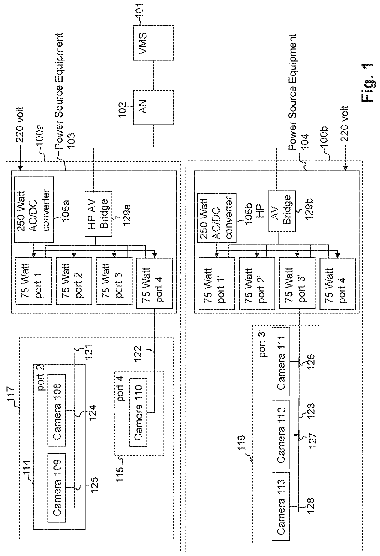
[0126]FIG. 1 illustrates a typical example of a video surveillance system using an IP over Coax video network. The video surveillance system comprises cameras which are supplied with power by a network equipment device such as a power source equipment device, using coax cables. The same coax c...


PUM


Abstract

The invention relates to power over data cable (PoC) systems comprising power source equipment, PSE, and plural PoC devices connected to the PSE. The PoC devices can operate in various power modes including low and high power modes. A method of managing power performed by a processing device of the system upon starting-up includes: reading, in memory of the processing device, a power change record to determine if, prior to the start-up, a target PoC device was about to switch from the low power mode to the high power mode; if it was about to switch, restricting it to remain in the low power mode; otherwise, triggering the target device to switch to the high power mode. As being restricted to the low power mode, the target device can no longer cause power failures. Thus endless loops of power failures caused by one and the same device are avoided.

Description

CROSS-REFERENCE TO RELATED APPLICATIONS[0001]This application is the National Phase application of PCT Application No. PCT / EP2017 / 057617, filed on Mar. 30, 2017, which claims the benefit under 35 U.S.C. § 119(a)-(d) of United Kingdom Patent Application No. 1605593.1, filed on Apr. 1, 2016 and entitled “POWER MANAGEMENT METHOD OF A SYSTEM MADE OF DEVICES POWERED OVER DATA CABLE”. The above cited patent application is incorporated herein by reference in its entirety.”FIELD OF THE INVENTION[0002]The present invention relates in general to power over data cable (PoC) systems, and in particular to a method, a device, a system and a computer program configured for power management of power-over-cable systems comprising a power source equipment device, PSE, (also known as “switch” or “receiver” or “extender”) acting as a power source and data switch, and comprising devices powered-over-cable by the power source equipment, preventing them from repetition of power failures occurred during th...

Claims


Application Information

Patent Timeline
Patent Type & Authority Patents(United States)
IPC IPC(8): G06F1/00H04L12/10G06F1/24G06F11/07G06F1/30G06F1/3203H04N5/247H04N23/90
CPCG06F1/3203G06F1/30G06F1/24G06F11/079H04L12/10H04N5/247H04L12/44H04L9/40H04N23/90
Inventor EL KOLLI, YACINELAGRANGE, PASCAL
Owner CANON KK
Learn More