Electronic device and method for use in network control point and central processing node
a technology of electronic devices and central processing nodes, applied in the field of wireless communication systems, can solve the problems of high power consumption and energy-saving communications, and achieve the effect of optimizing the selection of the number of antennas
- Summary
- Abstract
- Description
- Claims
- Application Information
AI Technical Summary
Benefits of technology
Problems solved by technology
Method used
Image
Examples
first embodiment
[0026]As described above, in a wireless communication system using the massive antennas technology, power consumption of the radio frequency and signal processing modules at an emitting terminal and a receiving terminal becomes quite high. Therefore, it is required to comprehensively consider optimization of power consumption, and the optimization becomes particularly complex especially in a case that there exist various power consumption models and multiple subsystems are required to be considered.
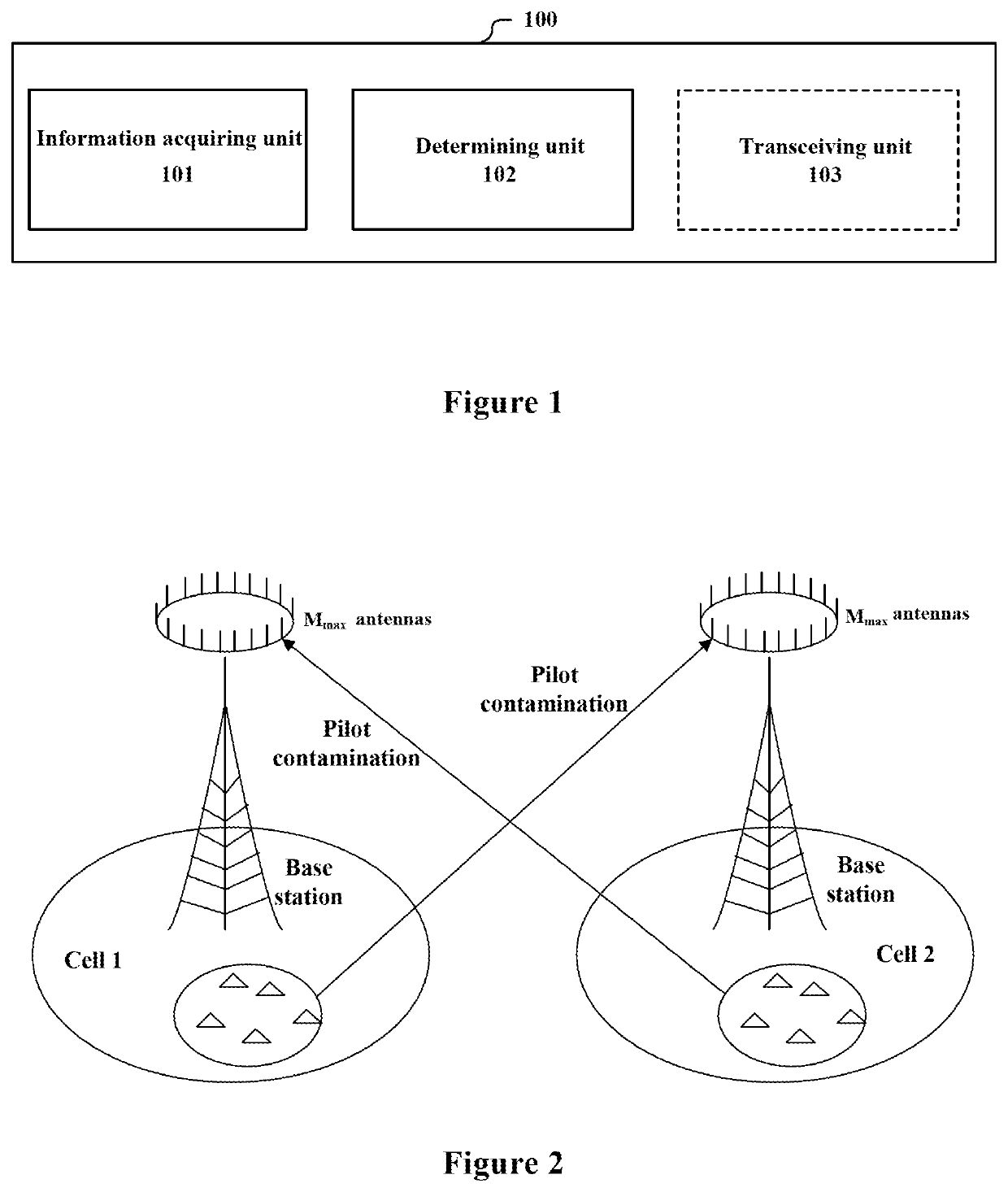
[0027]In addition, a communication system using the massive antennas technology is typically limited by a pilot contamination, i.e., interferences to uplink channel estimation caused by a fact that two communication subsystems perform data transmission using the same pilot sequence. The pilot contamination may be eliminated or suppressed by a method, for example, joint pre-coding, such that the performance of the communication system improves as the number of emitting antennas increases, ...
second embodiment
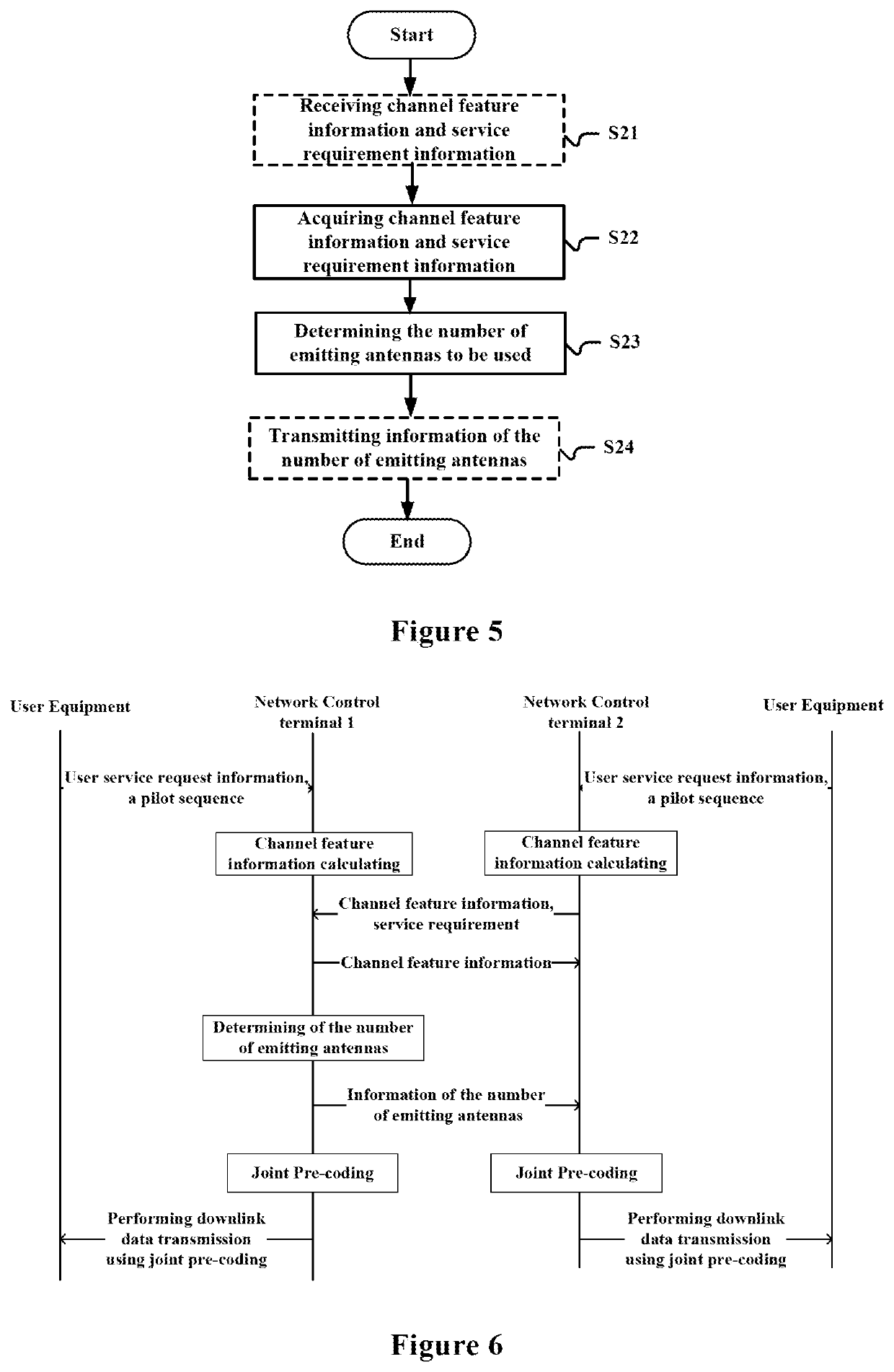
[0079]FIG. 3 is a block diagram of functional modules illustrating an electronic apparatus 200 for a central processing node according to one embodiment of the present disclosure. The electronic apparatus 200 includes: an information acquiring unit 201, configured to acquire channel feature information of channels between network control terminals which are adjacent to each other and user equipment served by respective network control terminals, and service requirement information of the user equipment, wherein the network control terminals perform downlink data transmission using joint pre-coding; and a determining unit 202, configured to determine, based on the service requirement information of the user equipment and the channel feature information, the numbers of emitting antennas to be used by respective network control terminals.
[0080]In this embodiment, it is the electronic apparatus 200 on the central processing node which determines the numbers of emitting antennas to be us...
third embodiment
[0092]In the process of describing the electronic apparatus in the embodiments described above, obviously, some processing and methods are also disclosed. Hereinafter, an overview of the methods is given without repeating some details disclosed above. However, it should be noted that, although the methods are disclosed in a process of describing the electronic apparatus, the methods do not certainly employ or are not certainly executed by the aforementioned components. For example, the embodiments of the electronic apparatus may be partially or completely implemented with hardware and / or firmware, the method described below may be executed by a computer-executable program completely, although the hardware and / or firmware of the apparatus can also be used in the methods.
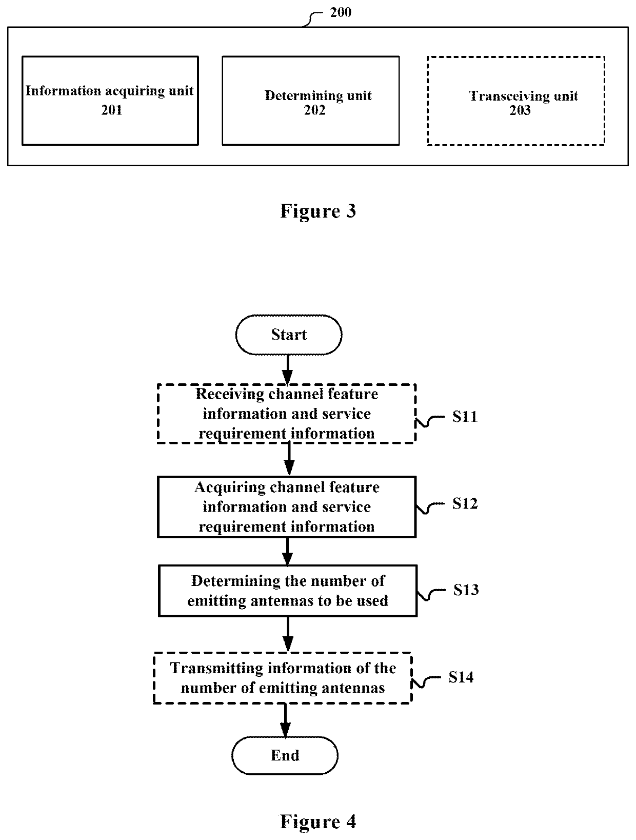
[0093]FIG. 4 is a flowchart illustrating a method for a network control terminal according to one embodiment of the present disclosure. The method includes: acquiring channel feature information of channels between a ...
PUM
 Abstract
Description
Claims
Application Information
 - R&D
- Intellectual Property
- Life Sciences
- Materials
- Tech Scout
- Unparalleled Data Quality
- Higher Quality Content
- 60% Fewer Hallucinations
Browse by: Latest US Patents, China's latest patents, Technical Efficacy Thesaurus, Application Domain, Technology Topic, Popular Technical Reports.
© 2025 PatSnap. All rights reserved.Legal|Privacy policy|Modern Slavery Act Transparency Statement|Sitemap|About US| Contact US: help@patsnap.com


