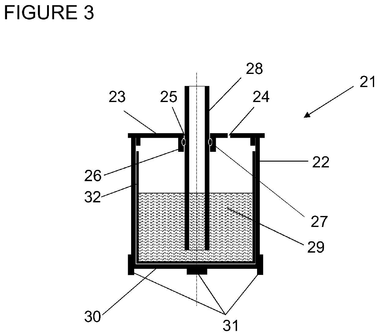
Receiving vessel for the gravimetric calibration of pipettes

a gravimetric and pipette technology, applied in the field of receiving vessels, can solve the problems of being relatively complicated and time-consuming to install and uninstall, reducing demanding calibration tolerances set by this standard, so as to reduce the rate of weight loss, reduce the rate of evaporation, and simplify the use

Active Publication Date: 2020-11-03
METTLER TOLEDO GMBH
View PDF5 Cites 0 Cited by
  • Summary
  • Abstract
  • Description
  • Claims
  • Application Information

AI Technical Summary

Benefits of technology

[0017]A receiving vessel according to the invention preferably includes a liner insert for the beaker. The purpose of this replaceable beaker liner is to prevent corrosion of the aluminum beaker by test liquid, particularly if test liquid is left sitting in the beaker over extended time periods.
[0023]The major advantage of the evaporation-trapping device of the present invention over the state of the art is its simplicity and ease of use, which makes it particularly suitable for laboratories where an analytical balance is not dedicated full-time to the process of performing pipette calibrations but has to be shared for other applications. By using a receiving vessel which also performs the evaporation-trapping function the evaporation-trapping enclosure is made redundant and can therefore be dispensed with, which removes the spatial constraints that such an enclosure puts on the weighing pan. Consequently, there is no need to exchange the standard weighing pan against a special load receiver. To perform the task of pipette calibration, one only has to place the receiving vessel of the present invention on the standard weighing pan of the laboratory balance.
[0024]In regard to its functional purpose of minimizing the rate of evaporation, the evaporation-trapping receiving vessel of the present invention was found to be at least on a par with the aforementioned evaporation trap of the prior art. In a comparison test, the rate of weight loss due to evaporation was tested with a) an open beaker without lid, b) an evaporation-trapping device of the prior art with an evaporation-trapping enclosure, and c) an evaporation-trapping receiving vessel of the present invention. The evaporation-trapping receiving vessel of the present invention proved equally effective as the prior-art device in reducing the rate of weight loss due to evaporation by an order of magnitude in comparison to an open beaker without a lid. Thus, the improvement in simplicity and ease of use of the evaporation-trapping receiving vessel of the present invention is gained without compromising its functional performance in comparison to a state-of-the-art evaporation trap.

Problems solved by technology

Especially for pipettes that handle very small volumes of liquid, the calibration tolerances set by this standard are very demanding, requiring the use of a high-accuracy analytical balance and detailed, reproducible procedures.
The loss of weight due to evaporation will cause a negative error in the result.
In cases where an analytical balance is not dedicated full-time to the process of performing pipette calibrations but has to be shared for other applications, a state-of-the-art evaporation trap kit presents the problem of being relatively complicated and time-consuming to install and uninstall every time the balance is switched between its normal laboratory weighing function and pipette calibration.
The steps of putting the evaporation trap enclosure in place over the receiving vessel and filling the ring-shaped open tub of the evaporation trap enclosure with tap water can thus be dispensed with, but the exchange of the standard weighing pan against a special load receiver for the receiving vessel is still cumbersome and undesirable for the user.
The defined reproducible placement of the receiving vessel on the load receiver is essential in the process of gravimetric pipette calibration, because a position change of the receiving vessel on the load receiver between the two weighings before and after discharging the test fluid from a pipette into the receiving vessel could introduce a significant error into the calculation of the relatively small difference between the two weighings.

Method used


Image

  • Receiving vessel for the gravimetric calibration of pipettes
  • Receiving vessel for the gravimetric calibration of pipettes
  • Receiving vessel for the gravimetric calibration of pipettes

Examples


Embodiment Construction

[0039]A state-of-the-art evaporation-trapping device 1 for the gravimetric calibration and verification of laboratory pipettes is illustrated schematically in FIG. 1. This type of evaporation-trapping device, which is available commercially as an accessory kit to an analytical balance, includes a receiving vessel 7, a special load receiver 9 to support the receiving vessel 7, and an evaporation-trapping enclosure 2 with a ring-shaped, open tub 5, a lid 3 and a centering ring or support base 10.

[0040]To convert an analytical laboratory balance from general weighing duty to pipette calibration, the standard weighing pan and weighing pan carrier of the balance are uninstalled and replaced by the special load receiver 9. The support base or centering ring 10 is installed on the weighing compartment floor 11 of the balance. The evaporation-trapping enclosure 2 is set in place on the support base 10, the ring-shaped, open tub 5 is filled with water 6, the receiving vessel 7 is seated on t...


PUM


Abstract

A receiving vessel (21) for the gravimetric calibration and verification of pipettes, whose purpose is to be placed on a load receiver (33) of a balance (40) and to receive and hold test liquid (29) discharged from pipettes that are being calibrated or verified, is configured as evaporation-trapping device, wherein the receiving vessel includes a beaker (22), a lid (23) with a passage opening (25), and a receiving tube (28) that is held in place in the passage opening, passing through the latter into the interior of the beaker. The receiving vessel is adapted to mechanically engage the weighing pan or load receiver when the receiving vessel is set on the weighing pan or load receiver. This ensures a secure placement of the receiving vessel in a defined, reproducible position on the weighing pan or load receiver.

Description

CROSS-REFERENCE TO RELATED APPLICATIONS[0001]This application claims priority to European Application No. 16192804.9, filed on 7 Oct. 2016, the content of which is incorporated by reference as if fully recited herein.TECHNICAL FIELD[0002]The disclosed embodiments relate to a receiving vessel used in the gravimetric calibration and verification of pipettes. The receiving vessel, when placed on a load receiver of a balance, receives and holds a test liquid that is discharged from a pipette that is being calibrated or verified. The receiving vessel is configured to trap evaporation of the liquid. The receiving vessel is designed to be secured, by a mechanical engagement, to the weighing pan or load receiver, so as to provide a defined, reproducible position on the weighing pan or load receiver with each use.BACKGROUND OF THE ART[0003]A pipette is a laboratory tool commonly used in chemistry, biology and medicine to pick up, transport and dispense a measured volume of liquid. Pipettes c...

Claims


Application Information

Patent Timeline
Patent Type & Authority Patents(United States)
IPC IPC(8): G01F25/00G01G21/22G01G17/04B01L3/02B01L3/00
CPCG01G21/22B01L3/021G01F25/0092B01L3/508G01G17/04B01L2200/148B01L2200/0684B01L2300/0832B01L2200/025B01L2200/0689B01L2300/046B01L2300/12G01F25/0084
Inventor TIEMENS, ROLAND
Owner METTLER TOLEDO GMBH
Why Eureka
Try Eureka