Bearing member, housing, and bearing device using the same

a technology of bearing device and bearing member, which is applied in the direction of bearing unit rigid support, sliding contact bearing, mechanical apparatus, etc., can solve the problems of fretting damage, deformation, and significant deformation of the housing of the engine, and achieve the effect of reducing the damage caused by fretting and reducing the relative slip vibration

Active Publication Date: 2020-11-03
DAIDO METAL CO LTD
View PDF4 Cites 0 Cited by
  • Summary
  • Abstract
  • Description
  • Claims
  • Application Information

AI Technical Summary

Benefits of technology

[0008]The maximum height Rz (μm) of the surface roughness of the outer peripheral surface is set in this manner, to thereby reduce a distance from a valley to a peak of irregularities on the outer peripheral surface of a rough-surfaced bearing member. Thus, a convex portion of the rough-surfaced outer peripheral surface becomes mostly deformed at the time of assembly. Due to this deformation, only a small part of the convex portion becomes worn and deformed during operation, and there is a smaller change in shape of the outer peripheral surface during operation. This results in a reduction in the amount of change in outer diameter of the bearing member during operation, and minimizes formation of a gap which may become a cause of slight relative slip vibrations. Therefore, slight relative slip vibrations between the housing and the bearing member are reduced, and accordingly fretting damage can be lessened.
[0009]A value of the ratio between the average protruding-peak height Rpk (μm) and the load length rate Mr1(%), that is a load curve parameter of the surface roughness is set in the manner as described above, so that a tip end of the convex portion forming the outer peripheral surface becomes almost flat. Thus, the contact area between the housing and the bearing member is increased. This results in an increase in friction force between the bearing member and the housing, and thus results in a reduction in slight relative slip vibrations between the bearing member and the housing. Accordingly, fretting damage can be lessened.
[0011]The average protruding-valley depth Rvk (μm) that is a load curve parameter for the outer peripheral surface is set in this manner, so that the rough-surfaced outer peripheral surface secures a proper depth in a concave portion. This helps discharge abrasion powder to this concave portion, the powder being generated from the bearing member and the housing at the time of fastening, during operation, and the like. Therefore, the amount of deposits of the abrasion powder in a gap, where the outer peripheral surface of the bearing member is opposed to the inner peripheral surface of the housing, can be reduced.
[0013]In the present embodiment, a bearing device comprises at least one of the bearing member and the housing. With this configuration, slight relative slip vibrations between the housing and the bearing member are reduced, and accordingly damage caused by fretting can be lessened.

Problems solved by technology

As a result of this, the housing of the engine tends to become deformed significantly during operation of the engine.
Thus, there is a problem in that when the housing and the bearing member become deformed significantly during operation of the engine, slight relative slip vibrations occur between the outer peripheral surface of the bearing member and the inner peripheral surface of the housing, which leads to fretting damage.
However, in a case where a minute, rough-surfaced portion is formed as disclosed in Japanese Patent Laid-Open No. 10-159853, a part of the convex portion of the rough-surfaced portion, which is not deformed at the time of assembly, becomes deformed during operation of the engine.
When the outer diameter of the bearing member is decreased, a gap is generated between the housing and the bearing member, which may become a cause of slight slip.
There is a problem in that this gap causes slight relative slip vibrations between the housing and the bearing member, which accelerates the fretting damage.

Method used


Image

  • Bearing member, housing, and bearing device using the same
  • Bearing member, housing, and bearing device using the same
  • Bearing member, housing, and bearing device using the same

Examples


example

[0033]Next, Example of the bearing member 12 described above is explained.

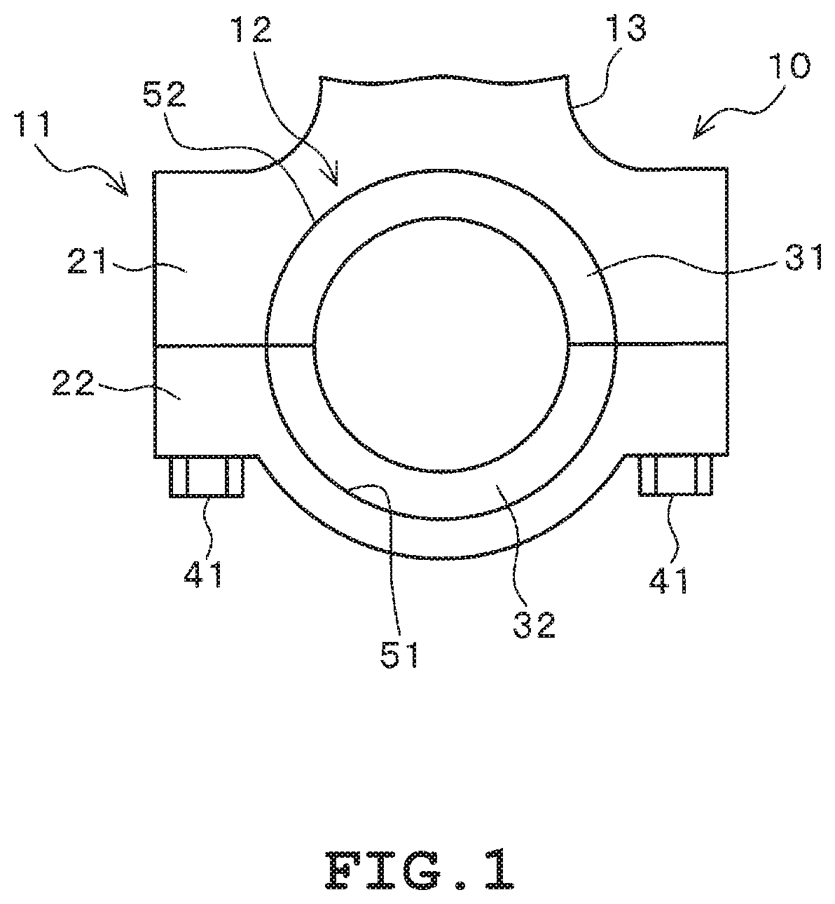
[0034]As shown in FIG. 6, each of samples 1 to 10 of the bearing member 12 was assembled to the housing 11 integral with the connecting rod 13 as shown in FIG. 1 to examine the bearing device 10 according to the present embodiment. The bearing member 12 was divided along the circumferential direction into two pieces, each of which was a semi-cylindrical halved bearing. In the present embodiment, the bearing member 12 with a cylindrical shape divided into two pieces has a seam that is set at a position perpendicular to the shaft of the connecting rod 13. Dimensions of the bearing member 12 were set including an outer diameter of 46 mm, a width of 16.5 mm, and a thickness of 1.5 mm. The bearing member 12 had a two-layered structure in which a bearing alloy layer made of copper alloy was stacked on a back metal layer made of carbon steel. The bearing outer peripheral surface 52 of the samples 1 to 10 of the beari...


PUM


Abstract

A bearing member according to an embodiment of the present invention is formed into a single cylindrical shape or a cylindrical shape divided into arcs along a circumferential direction, and is assembled to a housing on an outer peripheral side of the bearing member. The bearing member includes an outer peripheral surface provided on a side opposed to an inner peripheral surface of the housing. A maximum height Rz (μm) of a surface roughness of the outer peripheral surface is set as 2.00 μm≤Rz≤4.00 μm, and a value of ratio between an average protruding-peak height Rpk (μm) and a load length rate Mr1 (%), that is a load curve parameter for the surface roughness is set as 0.010≤Rpk / Mr1≤0.100.

Description

CROSS-REFERENCE TO RELATED APPLICATION(S)[0001]This application is based on and claims priority to Japanese Patent Application No. 2018-212165, filed on Nov. 12, 2018, the content of which is incorporated herein by reference in its entirety.BACKGROUND OF THE INVENTIONField of the Invention[0002]The present invention relates to a bearing member, a housing, and a bearing device using the bearing member and the housing.Background of the Invention[0003]In recent years, a reduction in weight of an engine has been required in order to further improve fuel efficiency. There is thus a tendency that each structure of the engine, such as a housing, has less rigidity in association with the reduction in weight. As a result of this, the housing of the engine tends to become deformed significantly during operation of the engine. In this engine, the housing holds a bearing member. Thus, there is a problem in that when the housing and the bearing member become deformed significantly during operati...

Claims


Application Information

Patent Timeline
Patent Type & Authority Patents(United States)
IPC IPC(8): F16C17/02F16C35/02
CPCF16C17/02F16C35/02F16C7/02F16C33/08F16C2240/54F16C33/043F16C33/20F16C2360/22F16C33/046
Inventor INAMI, SHIGERUIZUMIDA, MANABUITO, YUKIHIRONAKAGAWA, TAKAHITO
Owner DAIDO METAL CO LTD
Why Eureka
Try Eureka