Rfid tag
A technology of RFID tags and antennas, applied in the field of RFID tags, can solve problems such as reducing communication distance and achieve the effect of reducing the amount of variation
- Summary
- Abstract
- Description
- Claims
- Application Information
AI Technical Summary
Problems solved by technology
Method used
Image

Examples
no. 1 approach 》
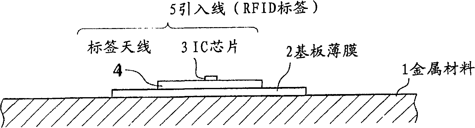
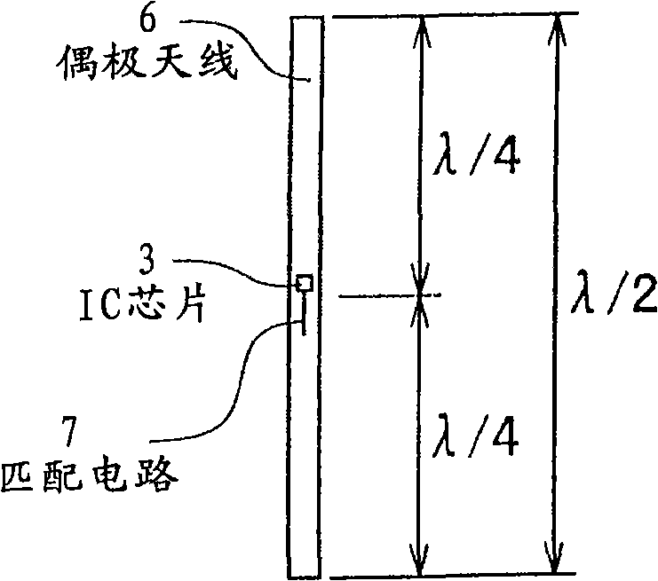
[0034] Hereinafter, embodiments of the RFID tag according to the present invention will be described in detail with reference to the drawings. figure 1 It is a cross-sectional view showing the state where the RFID tag is pasted on the surface of the metal material. On the surface of the resinous substrate film 2, stick the tag antenna 4 with the IC chip 3 mounted thereon by an adhesive or the like (hereinafter, the configuration with the IC chip 3 and the tag antenna 4 is referred to as the lead-in 5, and the not-shown one is covered by the cover film. The layered structure is called an RFID tag.), and the substrate film 2, which becomes a spacer, is sandwiched between the surface of the metal material 1 and the tag antenna 4. Accordingly, when a reader / writer (not shown) is inserted near the tag antenna 4, the information stored in the IC chip can be read and written by the reader / writer.
[0035] figure 2 for will figure 1 The surface view of the RFID tag when the tag an...
no. 2 approach 》
[0068] In the above-mentioned first embodiment, several modifications of the strip antenna were described, but in the second embodiment, several modifications of the extended tag antenna in which the width of the second antenna is increased are described.
[0069] (First variant of the extended tag antenna)
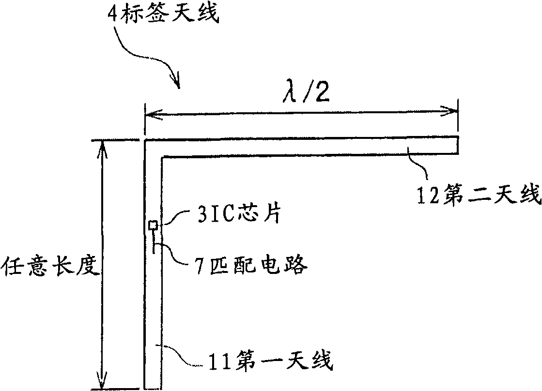
[0070] Figure 12 It is a structural diagram of the first modification of the extended tag antenna in the second embodiment. The transformation is for image 3 The structure of the first modification in the first embodiment shown in the first embodiment is deformed so that the width of the second antenna is widened. That is, if Figure 12 As shown, the end of the first antenna 21 on which the IC 3 is mounted is connected to the end of the long side of the rectangular second antenna 22 wider than the width of the first antenna, and the second antenna 22 extends in the vertical direction of the first antenna 21. . At this time, the electrical length of the first antenn...
no. 3 approach 》
[0085] In the third embodiment, an embodiment in which a tag antenna is formed on a substrate film, an embodiment in which the first antenna and the second antenna are electrically coupled, and a lead-in line composed of a tag antenna on which an IC chip is mounted using a protective film are described in detail. Layering is performed to form an embodiment of an RFID tag.
[0086] Figure 18 It is a schematic diagram of an embodiment in which a tag antenna is formed on a substrate film as viewed from above in the third embodiment. On the substrate film 2 formed by a heat-resistant polyimide film with a thickness of about 30 μm, the first antenna 21 and the second antenna of about tens of μm of metal are continuously vacuum-plated, or the first antenna 21 and the second antenna are formed by metal foil. An antenna 21 and a second antenna. Then, a slit is formed at a predetermined position of the first antenna 21 , a matching circuit 7 is provided, and the IC chip 3 is mounted...
PUM
 Abstract
Description
Claims
Application Information
 - R&D
- Intellectual Property
- Life Sciences
- Materials
- Tech Scout
- Unparalleled Data Quality
- Higher Quality Content
- 60% Fewer Hallucinations
Browse by: Latest US Patents, China's latest patents, Technical Efficacy Thesaurus, Application Domain, Technology Topic, Popular Technical Reports.
© 2025 PatSnap. All rights reserved.Legal|Privacy policy|Modern Slavery Act Transparency Statement|Sitemap|About US| Contact US: help@patsnap.com