Gas redirecting device for liquid-gas contacting column

a technology of gas redirection and liquid gas contacting column, which is applied in the direction of evaporating device, separation process, evaporation, etc., can solve the problems of gas overtreatment, prohibitively expensive pumping of gas to the shore, and ineffective treatment of gas

Active Publication Date: 2020-11-03
TOTAL PUTEAUX FR +2
View PDF15 Cites 0 Cited by
  • Summary
  • Abstract
  • Description
  • Claims
  • Application Information

AI Technical Summary

Benefits of technology

[0082]Further, as illustrated in FIGS. 4 to 6 and 9, for each gas-redirecting tube 3, the orthogonal projection 311 of the inlet end 31 onto the upper plane and the orthogonal projection 321 of the outlet end 32 onto the upper plane have an overlapping area of at most 50% of the total area of the upper plane covered by the orthogonal projections 311, 321 of the inlet end and the outlet end. In most cases, the orthogonal projection 311 of the inlet end 31 and the orthogonal projection 321 of the outlet end 32 present substantially the same area, thus, there are necessarily a portion of the orthogonal projection 311 of the inlet end 31 that is not within the overlapping area and a portion of the orthogonal projection 321 of the outlet end 32 that is not within the overlapping area. In some other cases, one of the orthogonal projections presents an area smaller than the area of the other orthogonal projection. Thus, it is possible that the orthogonal projection with the smaller area falls within the orthogonal projection with the larger area. In these cases, the technical effect of the invention is still obtained since there are still portions of gas flowing upwards that are redirected from a wetted zone of the first packed bed to a wetted zone of the second packed bed of the liquid-gas contacting column, notably those coming from or redirected to portion of the gas redirecting tube corresponding to non-overlapping area of the orthogonal projection with the larger area.
[0083]The overlapping area is preferably at most 40%, 30%, 20%, 10%, 5%, 0% of the total area of the upper plane covered by the orthogonal projections.
[0084]The outlet end 32 of each of the plurality of gas-redirecting tubes 3 may be adapted to let the gas flow in a direction substantially orthogonal to the upper plane once it exits the gas-redirecting tubes 3. In other words, the gas exiting the gas-redirecting tubes 3 is not mixed. In another embodiment, the outlet end 32 of each of the plurality of gas-redirecting tubes 3 may be adapted to let the gas flow in a direction substantially parallel to the upper plane once it exits the gas-redirecting tubes 3. In other words, the gas exiting the gas-redirecting tubes 3 is not mixed.
[0085]The outlet end 32 may be covered by a cover to avoid the introduction of the liquid falling downwards into the gas-redirecting tube 3. The cover may be chosen among the one known by the skilled person. For example, the cover may be flat, inverted V-shape (with the apex of the V away from the outlet end), etc.
[0086]The gas-redirecting tube 3 may be straight or comprise at least one curved portion. Thus, when the gas-redirecting tube 3 is straight, since the orthogonal projection 311 of the inlet end 31 onto the upper plane and the orthogonal projection 321 of the outlet end 32 onto the upper plane do not overlap, the gas-redirecting tube 3 is inclined at an angle different from 90° relatively to the upper plane. If the gas-redirecting tube 3 comprises at least one curved portion, it may comprise two or more straight portions and one or more curved portions, each connecting two straight portions to each other. In this latter case, it may alternatively consist of only one curved portion with or without any point of inflection.
[0087]The plurality of gas-redirecting tubes 3 may comprise m gas-redirecting tubes 3, with m an integer. The value of m depends on the size of the gas-redirecting device 100, in particular on the size of the plate 2. The value of m may be at least 2, in particular 2 to 50, more particularly 2 to 30, more particularly 2, 3, 4, 5, 6, 7, 8, 9, 10, 11, 12, 13, 14, 15, 16, 17, 18, 19, 20, 21, 22, 23, 24, 25, 26, 27, 28, 29, 30.

Problems solved by technology

FLNG technology also provides a number of economic advantages, for example, pumping gas to the shore can be prohibitively expensive due to the construction of pipelines.
However, the current FLNG technology challenge is that each element of the natural-gas processing plant and liquefaction unit needs to fit into a floating support having limited space, while maintaining appropriate levels of safety and achieving the desired specification.
In an underloaded area, the gas is not effectively treated, while in an overloaded area, the gas is over-treated.
It results in an inhomogeneity of the gas treatment and a global loss of efficiency of the liquid-gas contacting column.
This may significantly impact the column design basis (increased diameter and height of the column are needed to compensate the loss of efficiency) and consequently the whole FLNG project.
Industrial feedback on floating support is limited and does not allow precise predictions on this global loss of gas treatment efficiency of the liquid-gas contacting column.
However, this would increase constraints exerting onto the structure of the floating support itself.
This means that the size of the floating support would be so large, that economic feasibility of the project can be jeopardized.

Method used


Image

  • Gas redirecting device for liquid-gas contacting column
  • Gas redirecting device for liquid-gas contacting column
  • Gas redirecting device for liquid-gas contacting column

Examples


example 1

Gas-Redirecting Device with m=8

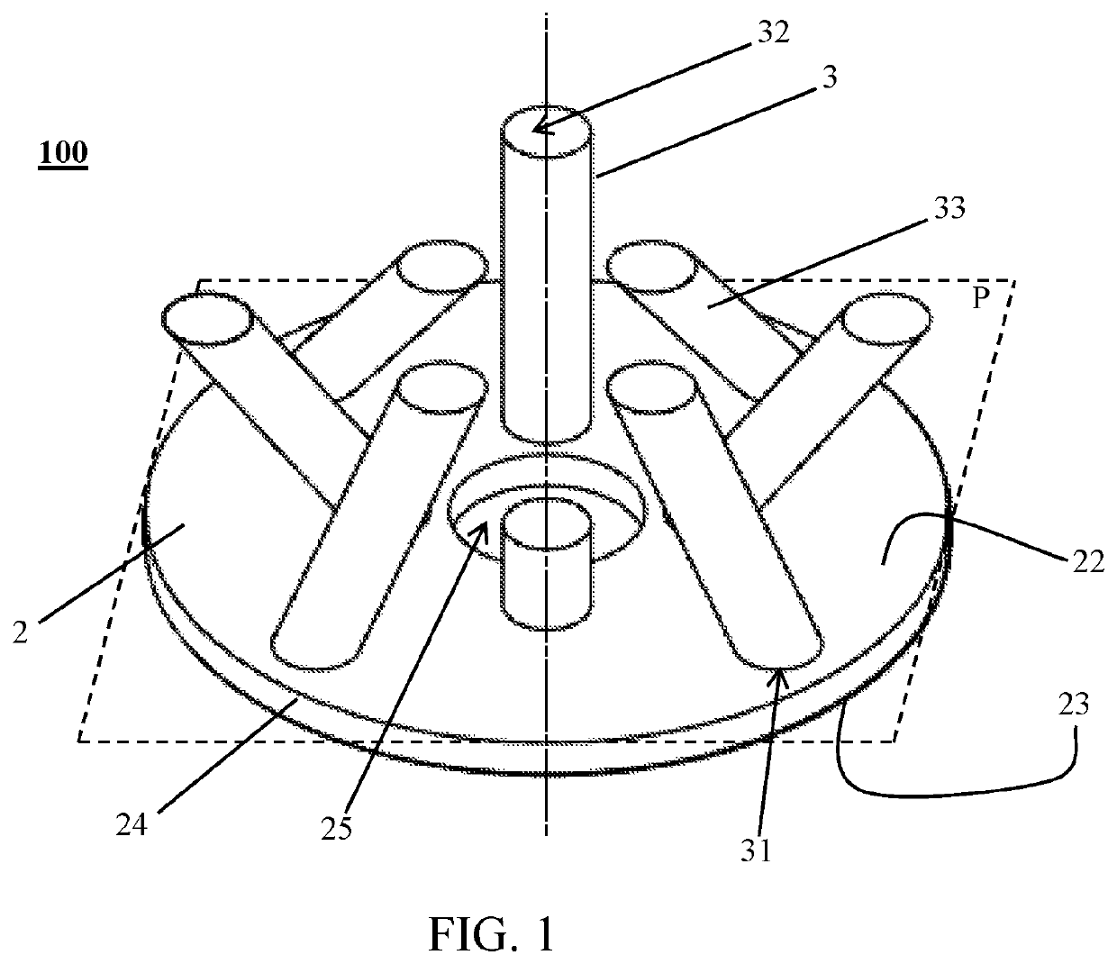
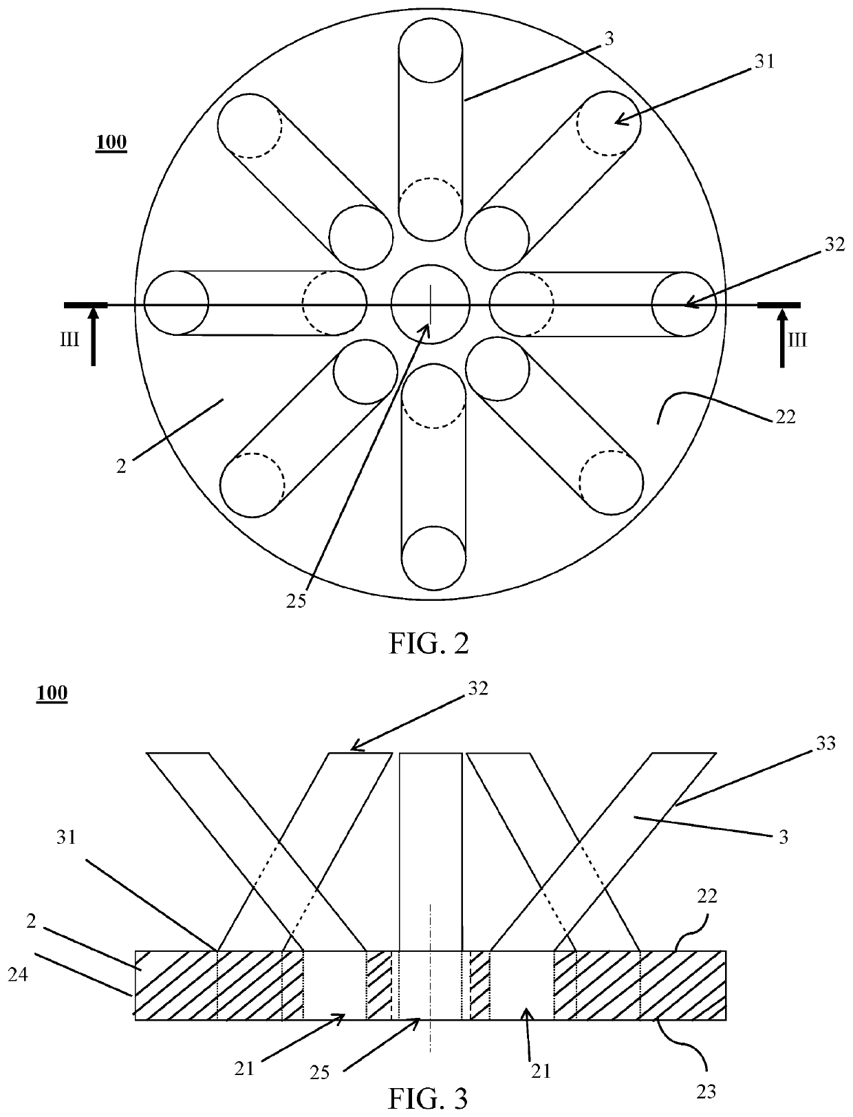
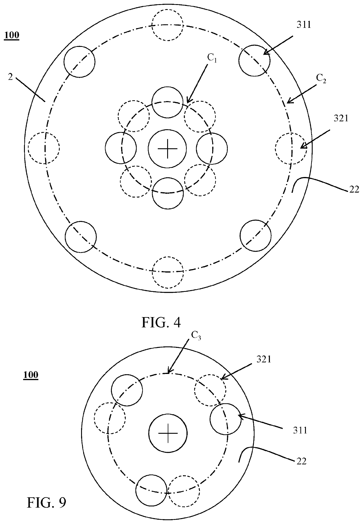
[0145]As illustrated by FIGS. 1 to 4, the gas-redirecting device 100 comprises eight straight gas-redirecting tubes 3, a circular plane plate 2 having eight circular through-holes 21 and a circular central orifice 25. Four of the through-holes 21 are homogenously disposed on a first circle C1 which is coaxial with the circular central orifice 25. The four other through-holes are homogeneously disposed on a second circle C2 which is coaxial with the circular central orifice and which presents a radius greater than the radius of the first circle C1. The through-holes 21 on the first circle C1 angularly alternate with the through-holes on the second circle C2. Each though-hole 21 is fluidly connected to one gas-redirecting tube 3 by the inlet end 31 thereof.

[0146]The gas-redirecting tubes 3 are inclined so that:[0147]the outlet end 31 and the inlet end 32 of each tube are radially aligned;[0148]the orthogonal projection 321 on the upper plane of the circu...

example 2

Gas-Redirecting Device, wherein m=3

[0150]As illustrated by FIGS. 7 to 9, the gas-redirecting device 100 comprises three straight gas-redirecting tubes 3, a circular plane plate 2 having three circular through-holes 21 and a circular central orifice 25. Each though-hole 21 is fluidly connected to one gas-redirecting tube 3 by the inlet end 31 of the one gas-redirecting tube 3.

[0151]The gas-redirecting tubes 3 are inclined so that:[0152]the orthogonal projection 321 on the upper plane of the circular plane plate 2 (which is the upper surface of the circular plane plate) of all outlet ends 32 and all inlet ends 31 of the gas-redirecting tubes are disposed on a same circle C3 coaxial to the circular central orifice 25;[0153]the orthogonal projection 321 of the outlet ends 32 alternate with the inlet ends 31.

[0154]Thus, the gas-redirecting device 100 presents a 3-fold rotational symmetry and the three gas-redirecting tubes 3 of the gas-redirecting device 100 can redirect the gas flowing ...


PUM


Abstract

The present invention relates to a gas-redirecting device presenting an upper plane and a plurality of gas-redirecting tubes comprising an inlet end and an outlet end. For each gas-redirecting tube, the orthogonal projections of the inlet end and the outlet end onto the upper plane have an over-lapping area of at most 50% of the total area of the upper plane covered by the orthogonal projections. Also provided is a liquid-gas contacting column comprising a gas-redirecting device, a floating support comprising a liquid-gas contacting column, at least two packed beds and a method for improving the efficiency of a liquid-gas contacting column which is based on redirecting the gas from a wetted zone of a lower packed bed to a wetted zone of the higher packed bed.

Description

RELATED APPLICATIONS[0001]The present application is a National Phase entry of PCT Application No. PCT / IB2015 / 002178, filed Oct. 30, 2015, said application being hereby incorporated by reference herein in its entirety.FIELD OF THE INVENTION[0002]The present invention relates to the improvement of gas processing efficiency in an oscillating liquid-gas contacting column placed on a floating support.BACKGROUND OF THE INVENTION[0003]Raw natural gas, coming primarily from crude oil wells, gas wells and condensate wells, comprises varying amounts of contaminants such as acid gases (carbon dioxide (CO2), hydrogen sulfide (H2S), and mercaptans such as methanthiol), water and mercury. To be marketed, raw natural gas must be purified in natural-gas-processing plants to meet the quality standards specified by the distribution companies or the LNG specifications. A natural-gas processing plant comprises different process units to remove impurities such as several liquid-gas contacting columns t...

Claims


Application Information

Patent Timeline
Patent Type & Authority Patents(United States)
IPC IPC(8): B01D53/18B01D3/24B01D1/00B01D3/20B01D53/14B01D3/32
CPCB01D3/20B01D3/24B01D3/324B01D53/1406B01D53/185B01D53/1462B01J2208/00849B01D1/0005B01D2259/4566B01D53/18
Inventor WEISS, CLAIREMAUBERT, THOMASFOURNIE, MAXIMEFOURATI, MANELBEARD, PHILIPPEALIX, PASCALPERDU, GAUTHIERSALAIS, CLÉMENTCARLIER, VINCENT
Owner TOTAL PUTEAUX FR
Why Eureka
Try Eureka