
Hard coat layered film

a laminated film and hard coating technology, applied in the field of hard coating laminated film, can solve the problems of low impact resistance and consequent fragility, low processing efficiency, and difficulty in handling, and achieve the effects of excellent transparency, color tone, abrasion resistance, and surface appearan

Active Publication Date: 2020-10-27
RIKEN TECHNOS CORP
View PDF224 Cites 0 Cited by
  • Summary
  • Abstract
  • Description
  • Claims
  • Application Information

AI Technical Summary

Benefits of technology

The patent text describes a hard coat laminated film that is suitable for use in image display devices. It is transparent, has good color tone, abrasion resistance, surface hardness, and appearance. This film can be used as a display faceplate in devices with a touch panel function. Overall, the technical effect of this invention is to provide a high-quality, durable film that enhances the performance of image display devices.

Problems solved by technology

On the other hand, glass has disadvantages such as a low impact resistance and consequent fragility; a low processability; difficulty in handling; a high specific weight and a consequent heavy weight; and difficulty in satisfying the demand for a curved or flexible display.
However, the abrasion resistance is still insufficient in each of them.

Method used


Image

  • Hard coat layered film
  • Hard coat layered film
  • Hard coat layered film

Examples


example 1

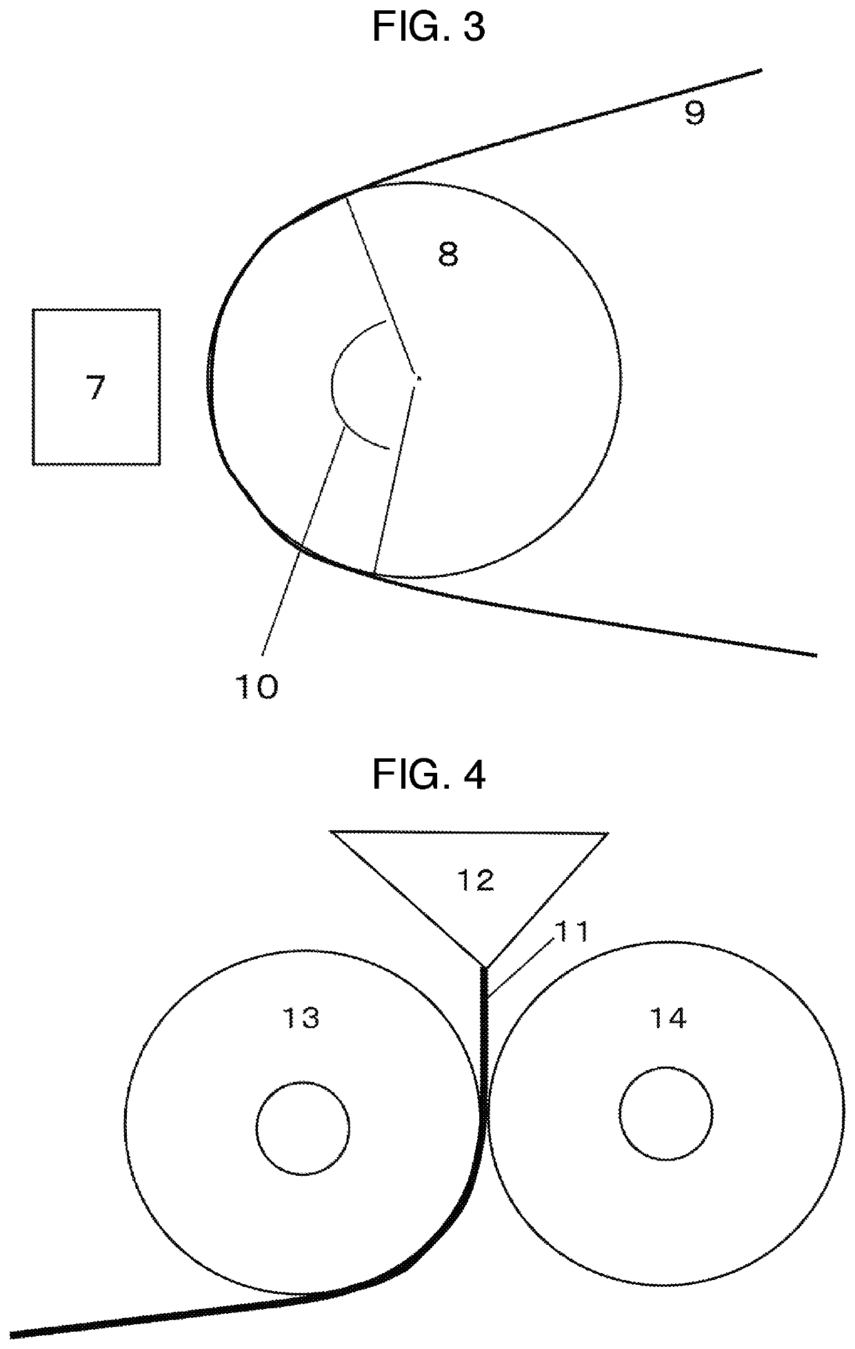
[0234]Both surfaces of the (P-1) were subjected to a corona discharge treatment. Both surfaces had a wetting index of 64 mN / m. Subsequently, the surface on the α1 layer side was coated with the (H2-1) by using a die-type applicator so that the wet coat thickness was 40 μm (thickness after curing: 22 μm). Next, the resultant was passed in a drying furnace with the inner temperature set to 90° C. at a line speed such that the time required to pass through from the inlet to the outlet was 1 minute, and then treated with a curing apparatus (see FIG. 3) having a UV irradiator 7 of high-pressure mercury lamp type and a mirror-finished metal roll 8 having a diameter of 25.4 cm which were disposed opposite to each other, under conditions that the temperature of the mirror-finished metal roll 8 was 90° C. and the integrated amount of light was 80 mJ / cm2. In FIG. 3, reference numeral 9 denotes a web, and reference numeral 10 denotes a holding angle. As a result, the wet coat formed of the (H2...

examples 2 to 15 , examples 1c to 5c

Examples 2 to 15, Examples 1C to 5C

[0235]Each hard coat laminated film was prepared and measurement / evaluation of the physical properties was performed totally in the same way as in Example 1 except that the coating material shown in any one of Tables 5 to 8 was used instead of the (H1-1). The results are shown in any one of Tables 5 to 8.

examples 16 to 26 , examples 6c to 8c

Examples 16 to 26, Examples 6C to 8C

[0236]Each hard coat laminated film was prepared and measurement / evaluation of the physical properties was performed totally in the same way as in Example 1 except that the coating material shown in any one of Tables 8 to 10 was used instead of the (H2-1). The results are shown in any one of Tables 8 to 10.


PUM

PropertyMeasurementUnit
particle diameteraaaaaaaaaa
thicknessaaaaaaaaaa
thicknessaaaaaaaaaa

Abstract

Embodiments provide a hard coat layered film having a first hard coat, a second hard coat, and a transparent resin film layer in order from an outer layer side, the first hard coat including (A) 100 parts by mass of a polyfunctional (meth)acrylate including 20% by mass or more of a tripentaerythritol acrylate, (B) 0.01-7 parts by mass of a water repellent, and (C) 0.01-10 parts by mass of a silane coupling agent, the first hard coat being formed from a coating material not including inorganic particles, and the second hard coat including (A′) 100 parts by mass of a polyfunctional (meth)acrylate and (D) 50-300 parts by mass of inorganic fine particles having an average particle diameter of 1-300 nm. According to at least one embodiment, component (A) may be a mixture of tripentaerythritol acrylate and one or more species selected from the group consisting of dipentaerythritol acrylate, monopentaerythritol acrylate, and polypentaerythritol acrylate.

Description

CROSS REFERENCE TO RELATED APPLICATIONS[0001]This application claims the benefit of and priority to PCT / JP2016 / 084981, filed on Nov. 25, 2016, entitled (translation), “HARD COAT LAYERED FILM,” which claims the benefit of and priority to Japanese Patent Application No. 2015-239074, filed on Dec. 8, 2015, which is hereby incorporated by reference in its entirety into this application.BACKGROUNDField[0002]Embodiments relate to a hard coat laminated film. More specifically, embodiments relate to a hard coat laminated film excellent in transparency, color tone, abrasion resistance, surface hardness, and surface appearance.Background Art[0003]In recent years, touch panels, which are installed on an image display device such as a liquid crystal display, a plasma display and an electroluminescence display and enable input by touching with fingers, a pen or the like while watching displayed objects, have become popular.[0004]For a display faceplate in a touch panel, articles using glass as t...

Claims


Application Information

Patent Timeline
Patent Type & Authority Patents(United States)
IPC IPC(8): B32B27/18C09D5/00B32B27/08B32B27/30G02B1/14C09D133/10C08J7/04C09D7/40G02B1/18C08J7/043C08J7/046
CPCC09D7/68B32B27/30C08J7/042G02B1/18B32B27/18C09D133/10C09D5/00C09D7/67C09D7/40G02B1/14C08J2333/14C08J7/043C08J7/046B32B27/08B32B27/281B32B27/308B32B27/365B32B2307/412B32B2457/208
Inventor WASHIO, NOZOMUHASHIMOTO, TAKETO
Owner RIKEN TECHNOS CORP
Learn More