Particle beam apparatus and method for operating a particle beam apparatus

a particle beam and apparatus technology, applied in the direction of chemistry apparatus and processes, electric discharge tubes, cleaning processes and apparatuses, etc., can solve the problems of inability to detect particles, and inability to deflect particle beams

Active Publication Date: 2020-10-27
VISTEC ELECTRON BEAM
View PDF24 Cites 1 Cited by
  • Summary
  • Abstract
  • Description
  • Claims
  • Application Information

AI Technical Summary

Benefits of technology

[0006]Example embodiments of the present invention provide a particle beam apparatus, as well as a method for operating a particle beam apparatus, via which a targeted and efficient cleaning of component surfaces in the column and / or in the vacuum sample chamber of such an apparatus is possible.
[0022]In the cleaning operation, because of the use of a plurality of light sources able to be switched on and off selectively with respect to time, a defined local cleaning of especially contaminated elements or areas in the column and / or the vacuum sample chamber of the particle beam apparatus may be performed. Disassembly of the overall system is not necessary for this. That is, the standstill time of the apparatus resulting for the cleaning operation may be shortened considerably. Furthermore, because of the possibility created for the defined local cleaning of affected elements, the stress for other uncontaminated components in the column and / or in the vacuum sample chamber may be minimized to a great extent.

Problems solved by technology

The contamination layers exhibit poor electrical conductivity, and may become highly charged because of the primary and secondary electrons impinging on them.
Such fields in turn undesirably deflect the particle beam in the column and lead, for example, to uncontrollable drifts of the beam position on the substrate or influence other beam properties in uncontrollable manner.
In addition to the time-consuming disassembly and cleaning of respective components, there are various conventional methods for removing corresponding contaminations without having to dismantle the column of the particle beam apparatus.
This method has the disadvantage that with its use, a spatially targeted cleaning of specific components in the column is almost impossible.
Moreover, it is difficult to set a suitable ozone pressure in all areas of the column if, at the same time, the necessary high vacuum must be maintained in exposure operation.
A selective removal of contaminants on specific components is almost impossible using this method, as well.
For example, the cleaning cannot be controlled locally according to demand.

Method used


Image

  • Particle beam apparatus and method for operating a particle beam apparatus
  • Particle beam apparatus and method for operating a particle beam apparatus
  • Particle beam apparatus and method for operating a particle beam apparatus

Examples


Embodiment Construction

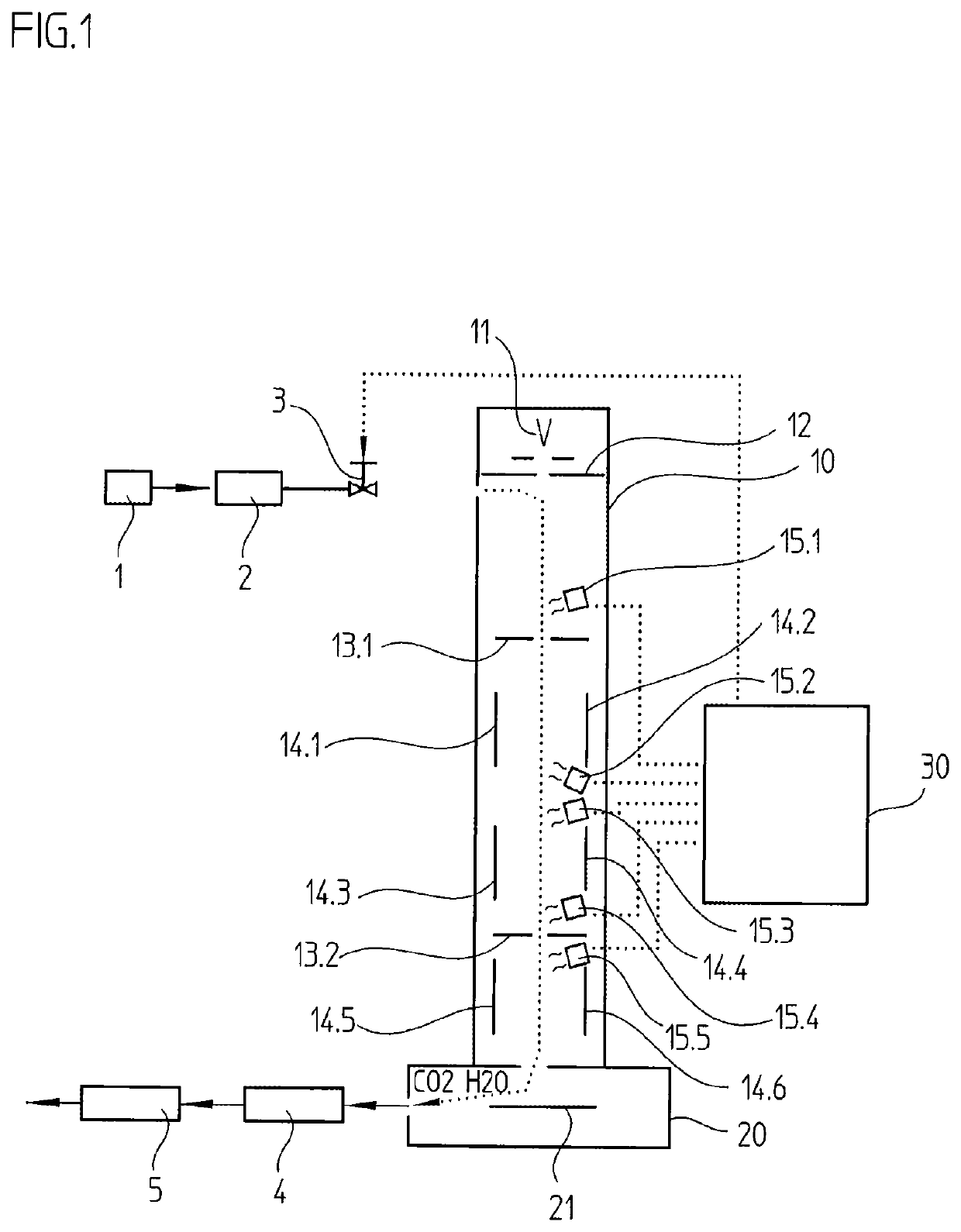
[0028]A particle beam apparatus according to an example embodiment of the present invention is explained below with reference to FIG. 1, which schematically illustrates the particle beam apparatus.

[0029]In this, as well as in the further exemplary embodiments, the particle beam apparatus takes the form of an electron beam apparatus. It should be understood, however, that the particle beam apparatus may be used in connection with other particle-beam systems, such as, for example, ion-beam apparatuses, electron-beam microscopes, etc.

[0030]The particle beam apparatus includes a column 10 having a particle-beam optical system for generating a particle beam, or more precisely, an electron beam, to thereby write a desired pattern on a substrate 21 in vacuum sample chamber 20 in an exposure operation. In addition to a particle beam source 11 disposed in column 10, the particle-beam optical system includes, for example, various diaphragms 13.1, 13.2, as well as electrostatic deflector elect...


PUM


Abstract

In a particle beam apparatus and a method for operating a particle beam apparatus, the particle beam apparatus has a column having a particle-beam optical system for generating a particle beam, to thereby expose a desired pattern in a vacuum sample chamber in an exposure operation. In a cleaning operation, a regulable gas stream having photodissociatable gas is fed to the column and / or the vacuum sample chamber via a gas-feed system. The photodissociation of the supplied gas is brought about in the cleaning operation with the aid of a plurality of light sources distributed spatially in the column and / or in the vacuum sample chamber. In the cleaning operation, individual light sources are able to be switched on and off selectively with respect to time via a control unit connected to the light sources, in order to clean individual elements in the column and / or in the vacuum sample chamber in targeted fashion.

Description

CROSS-REFERENCE TO RELATED APPLICATIONS[0001]The present application claims priority to Application No. 10 2015 211 090.7, filed in the Federal Republic of Germany on Jun. 17, 2015, which is expressly incorporated herein in its entirety by reference thereto.FIELD OF THE INVENTION[0002]The present invention relates to a particle beam apparatus as well as a method for operating a particle beam apparatus, and in particular, a possibility for cleaning such apparatuses.BACKGROUND INFORMATION[0003]Conventional particle beam apparatuses, e.g., electron beam apparatus, include a column having a particle-beam optical system in order to thereby expose a desired pattern in a vacuum sample chamber in an exposure operation. In the course of the operating time, organic contaminants deposit on surfaces of components in the column and / or the vacuum sample chamber, e.g., on diaphragms or on electrodes of electrostatic deflection systems. For example, these contaminants come from the lacquers, necess...

Claims


Application Information

Patent Timeline
Patent Type & Authority Patents(United States)
IPC IPC(8): B08B7/04H01J37/18B08B7/00B08B5/00H01J37/317H01J37/02
CPCB08B5/00H01J37/18H01J37/02B08B7/005H01J37/3174B08B7/04H01J2237/31793H01J2237/1825H01J2237/022H01J37/3002H01J2237/30
Inventor BORSCHEL, CHRISTIAN
Owner VISTEC ELECTRON BEAM
Why Eureka
Try Eureka