Particulate matter detection apparatus that mitigates water collection

a detection apparatus and technology of particles, applied in mechanical devices, instruments, machines/engines, etc., can solve the problems of increasing detection errors and element cracking, and achieve the effects of preventing water-induced cracking of element portions, preventing water-induced cracking of sensor elements, and suppressing contamination of element portions due to pollutants

Active Publication Date: 2020-10-06
DENSO CORP
View PDF5 Cites 1 Cited by
  • Summary
  • Abstract
  • Description
  • Claims
  • Application Information

AI Technical Summary

Benefits of technology

[0009]According to the present disclosure, if the volume of water in the exhaust passage is determined to be larger than the threshold of the water drainage, the heater heats the element portion, and the element portion is controlled in the temperature range resisting water-induced cracks of the element portion, independently of the any volume of the water droplets covering the element portion. When the volume of water in the exhaust passage is determined to be larger than the threshold of the water drainage, the exhaust passage is in a state of water-invasion and an exhaust gas temperature is relatively low. For this reason, the temperature of the element portion may be provided as a temperature which is higher than or near to the exhaust gas temperature, even when the element portion is heated in the temperature range resisting the water-induced cracks of the element portion independently of the any volume of the water droplets covering the element portion. As a result, thermophoresis of pollutants from the element portion to the exhaust gas occurs or thermophoresis of pollutants to the element portion may be suppressed. Furthermore, the water-induced cracking of the element portion is prevented, and contamination of the element portion due to pollutants is may also be suppressed.
[0010]When it is determined that water drainage of the exhaust passage is completed, the temperature of the element portion is lower than a starting temperature of particulate matter combustion. Additionally, the element portion is heated for a predetermined period in the water-repellent temperature range to repel water which is adhered to the element portion by the Leidenfrost effect. After the water drainage of the exhaust passage is completed, the water-induced cracking of the sensor element is prevented even when the temperature of the element portion is increased to the water-repellent temperature range. As a result, since water which has adhered onto the element portion is repelled, pollutants will not adhere onto the element portion, thus the contamination of the element portion due to the pollutants may be suppressed. Furthermore, the water-induced cracking of the element portion is prevented when the element portion is dried, and contamination of the element portion by the pollutants may also be suppressed.

Problems solved by technology

However, if the detection of PM is continued from a previous state before the engine was stopped, there is a concern that detection errors will increase.
However, if an element portion is covered with water droplets from water in an exhaust pipe or an exhaust gas when the element portion is heated, there is a case of the element portion cracking, for example.

Method used


Image

  • Particulate matter detection apparatus that mitigates water collection
  • Particulate matter detection apparatus that mitigates water collection
  • Particulate matter detection apparatus that mitigates water collection

Examples


first embodiment

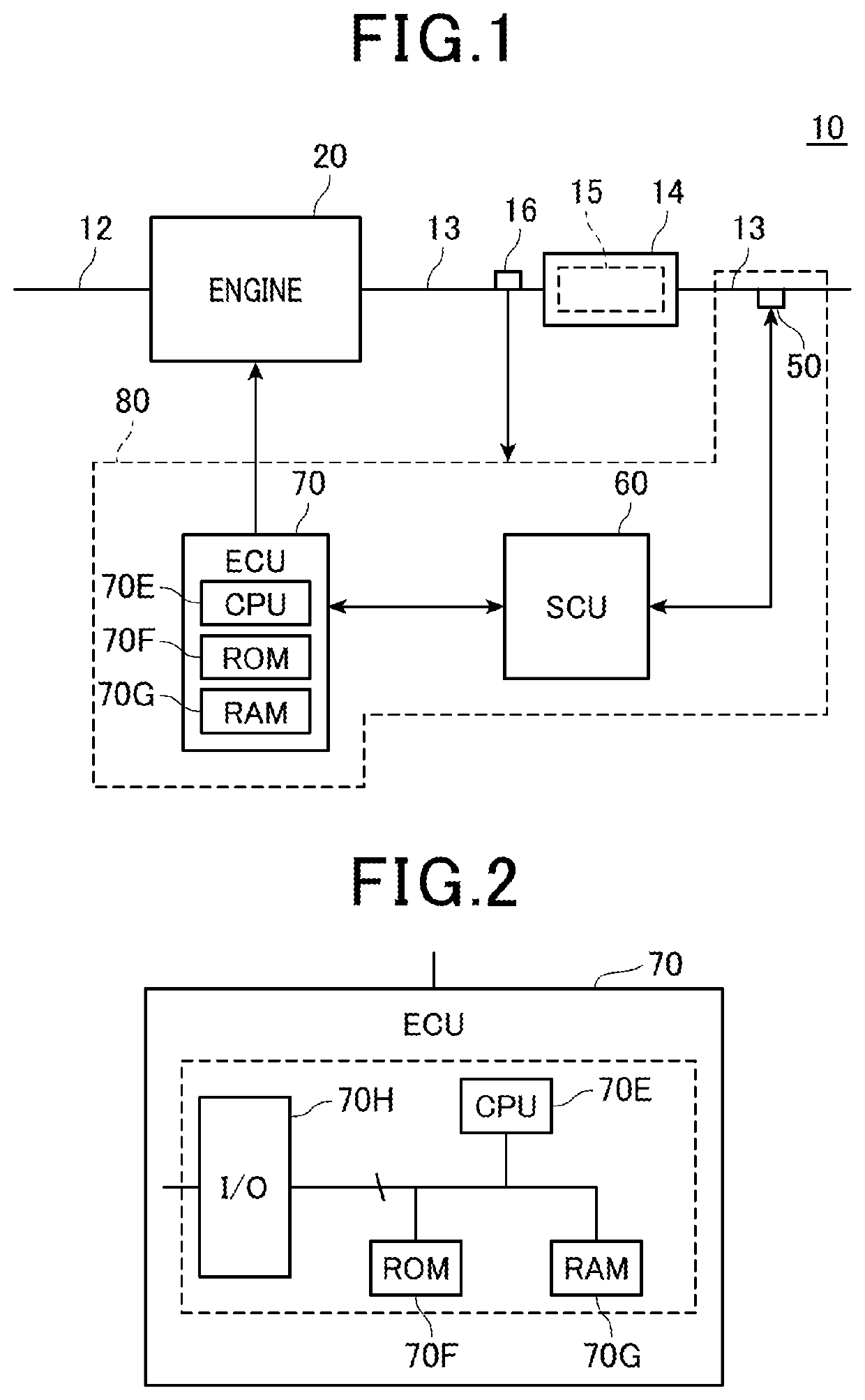
[0026]Firstly a configuration of an engine system 10 of a first embodiment is described. As shown in FIG. 1, the engine system 10 is provided with an engine 20. The engine 20 (internal combustion engine) is a diesel engine, for example. The engine 20A is connected to an intake passage 12 and an exhaust passage 13. An exhaust gas purifying device 14 is mounted on the exhaust passage 13. The exhaust gas purifying device 14 is configured to remove toxic components from exhaust gas, which is emitted from the engine 20. The toxic components are PM, for example, nitrogen oxides, and carbon compounds such as HC (hydrocarbons) and CO (Carbon Monoxide), which are generated from fuel that has not burned or from incomplete combustion. Particularly in the present embodiment, a PM capturing filter 15 is provided on the exhaust purification device 14. The exhaust gas purification device 14 is a known configuration, therefore further details are omitted.

[0027]The engine system 10 is equipped with ...

second embodiment

[0076]Next, parts of a second embodiment which are different from first embodiment will be described with reference to FIG. 13.

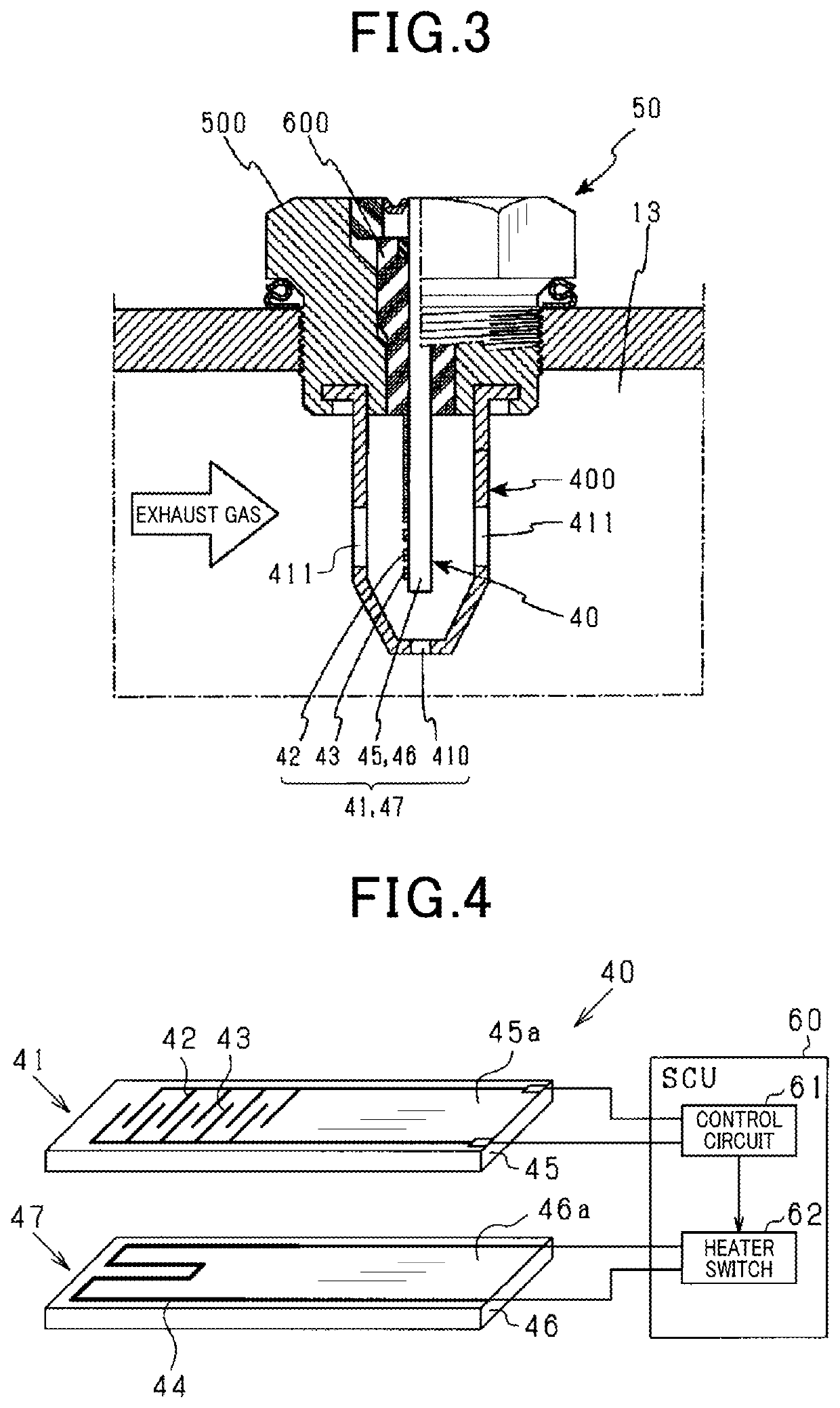
[0077]If the engine 20 is a diesel engine, an intake volume is large and the temperature of exhaust gas is low compared to a gasoline engine. For example, an exhaust gas temperature of a diesel engine rises to 400° C., compared to 800° C. for a gasoline engine. As a result, if the engine 20 is a diesel engine, the exhaust passage 13 is easily quenched when fuel is cut, and condensed water may be generated, compared to a gasoline engine. Moreover, the element portion 41 may become in the state of the invasion of water. Also, if the engine 20 is installed in a hybrid vehicle, quenching of the exhaust passage 13 and generation of condensed water may occur during idle reduction and when fuel is cut at a point of regeneration brake. In such circumstances, the element portion 41 may become in the state of invasion of water.

[0078]In a situation of heavy rain, for e...


PUM

PropertyMeasurementUnit
temperatureaaaaaaaaaa
water-repellent temperatureaaaaaaaaaa
combustion temperatureaaaaaaaaaa

Abstract

An apparatus which detects particulate matter is provided. This apparatus estimates a volume of water inside an exhaust passage using estimation sections. When an estimated volume of water is larger than a water drainage threshold, an element portion is heated using a heater by the first temperature range controller, in a temperature range which resists water-induced cracking independent of a volume of water droplets. If the estimated volume of water is less than a water drainage threshold, the water drainage determination section determines that the water drainage of the exhaust passage is completed. Additionally, if it is estimated that the water drainage is completed, the element portion is heated by a second temperature controller at temperature lower than a starting temperature of combustion of particulate matter and in order to repel water adhered onto the element portion in a water-repellent temperature range for a predetermined period.

Description

CROSS-REFERENCE RELATED APPLICATION[0001]This application is the U.S. national phase of International Application No. PCT / JP2016 / 081168 filed on Oct. 20, 2016 which designated the U.S. and claims benefit of priority of earlier Japanese Patent Application No. 2015-207173 filed on Oct. 21, 2015, the entire contents of each of which are hereby incorporated by reference.BACKGROUNDTechnical Field[0002]The present disclosure relates to a particulate matter detection apparatus which detects particulate matter, and more particularly relates to a particulate matter detection apparatus which detects a quantity of particulate matter contained in an exhaust gas of an internal combustion engine.Background Art[0003]Conventionally, an apparatus equipped with a particulate matter sensor is known. This apparatus detects particulate matter (referred to as PM hereafter) contained in an exhaust gas of a diesel engine. There is a known apparatus which is provided with the foregoing configuration. In thi...

Claims


Application Information

Patent Timeline
Patent Type & Authority Patents(United States)
IPC IPC(8): G01N15/06F01N11/00F01N3/023F01N13/00
CPCF01N11/00F01N13/008G01N15/0606G01N15/0656F01N2550/04F01N2560/20F01N2560/05F01N3/023
Inventor MIYAGAWA, GOTAMURA, MASAYUKIYAMAMOTOARAKI, TAKASHISAKAWA, TOSHIHIROKATSUNO, MASATOYOSHIDOME, MANABU
Owner DENSO CORP
Why Eureka
Try Eureka