Barrier system

a barrier and rail technology, applied in roadway safety arrangements, roadways, construction, etc., can solve the problems of longitudinal movement in the rail, damage to both the barrier and the vehicle, hazard to vehicle occupants and other road users, etc., and achieve the effect of reducing the deformable load

Active Publication Date: 2020-10-06
HOLMES SOLUTIONS LTD
View PDF24 Cites 0 Cited by
  • Summary
  • Abstract
  • Description
  • Claims
  • Application Information

AI Technical Summary

Benefits of technology

[0046]As may be appreciated, the above described barrier system may provide a variety of advantages. Some examples include:
[0056](j) The system can translate one form of motion or force vector which does not apply a sufficient force to the washer to cause deformation into a second force vector or motion which does apply a force of sufficient strength to deform a region on the washer. Equally, the system can be constructed to undertake the opposite, thereby changing the motion or applied force so as to reduce the deformable load applied to the washer.

Problems solved by technology

However the system must also be able to withstand variations in temperature whereby the longitudinal beam (elongated tension element) can expand during hot temperatures and contract during colder weather, resulting in a longitudinal movement in the rail.
When an errant vehicle impacts the barrier it can be a violent and dynamic impact resulting in damage to both the barrier and the vehicle.
If the height of the longitudinal beam becomes too low relative to the centre of gravity of the vehicle the impacting vehicle has the potential to override the barrier causing a hazard to the vehicle occupants and other road users.
The downside to using block-outs is that the width of the system increases and therefore the width of the road corridor must also be increased to avoid constricting the space allowable for the vehicle.
The key issue with this method is the potential for the fractured, broken, or separated post to form a 
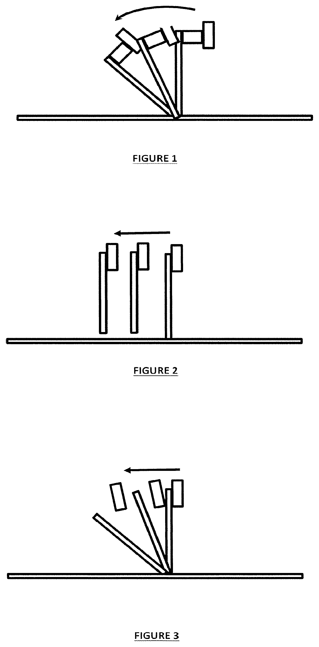
hazard to other road users as it deflects backwards.The connection detail used to join the longitudinal beam and the posts can be designed so as to allow the two components to separate when impacted (see FIG. 3).
This method has a considerable number of advantages if it is controlled correctly but this is very difficult to achieve.
A further drawback of this system is that there may be a fine tolerance for the degree of fastener tightening.
Too loose and the parts may detach prematurely.
Too tight and the rail sliding movement may be impacted potentially causing the rail to be drawn down with the post due to the additional friction or clamping force created between the post and the beam.
The key benefit of this system is that it allows for vertical movement between the post and the longitudinal beam and it creates a vertical release of the connection, however it does not allow the post to separate from the longitudinal beam in any other manner or direction of loading and therefore does not address the issues of releasing when the force perpendicular to the face of the post is sufficiently large, releasing due to twisting of the post, or the beam moving laterally or downwards.
Due to this limitation, the system cannot be installed with a longitudinal beam on both sides of the post (back-to-back or median installation).
The system is also difficult to install due to the dimensions of the bridge at the top of the slot.
This bridge is required to be small to limit the strength to ensure release occurs, and therefore because it is small it is prone to being damaged when installed into the ground, particularly since the majority of the posts are driven into the ground by being pounded using a falling weight onto the top surface.
Any damage to this bridge can critically alter the manner in which the release mechanism occurs.
This form of release is prone to error and has the potential to drag the longitudinal beam downward if the properties of the washer are inconsistent or the placement of the washer is varied.
In this configuration the washer cannot deform as it is constrained between the head of the fastener and the beam, rendering the unsuitable for use.
Installation of this system can also be difficult with numerous washers and spacers required to be installed, particular between the post and the longitudinal beam.
If any component is not installed (or incorrectly installed) then the system performance will be significantly compromised.
Concern also arises if the system is installed with a different washer which would significantly alter the performance of the system.
However, obtaining the correct performance of the system is difficult as there is insufficient difference between the force imparted on the tabs when holding the tab into the post under normal conditions and the forces which the tab must break under during an impact from a vehicle.
Experience has shown that this can be difficult to achieve with insufficient tolerance between the forces obtained during an installation and those during an impact.
Key issues with installations include the ability of the tabs to provide sufficient strength in a direction perpendicular to the post when the longitudinal beam is required to be installed around a convex curved where a high tension force perpendicular to the face of the post can be generated.
Further, when a post is driven into the ground there can be a high vibration force placed into the post.
This vibration force has the potential to damage the connection with the tab.
If this tab is damaged, the entire post is required to be replaced which is time consuming and expensive.
Further, if the damage is not readily identifiable, the post may remain installed in the barrier system with consequent impact performance of the system being compromised.
These tabs interfere with the fastener used to connect the longitudinal beam to the post to provide some resistance to vertical movement.
A key issue with the system described in the '617 application is that the sliders are required to be inserted over the top of the posts and then are required to release from the top of the posts.
Likewise, if the top of the posts are damaged during an impact then the sliders may not release in a consistent manner (or release at all) and result in the longitudinal beam being dragged downward with the posts.
This limits the usefulness of the system.
As should be appreciated from the above, art barrier systems may have drawbacks such as bespoke parts, difficult installation and lack of tunability.

Method used


Image

  • Barrier system
  • Barrier system
  • Barrier system

Examples


working examples

[0160]The above described barrier system is now described by reference to specific examples. Note that reference is made below to a separate washer however, as noted above, the washer may be integral to the fastener and not a separate item.

example 1

[0161]As noted above, the system comprises of three key components; the longitudinal beam, the posts, and the connection. A general description of the three components is provided below. Please note that these are only provided by way of example.

[0162]The Longitudinal Beam

[0163]The longitudinal beam 1 is required to form a continuous element along the length of the barrier. It is most commonly manufactured from short lengths of structural section which are joined at regular intervals to form a continuous member. The shape of the longitudinal beam 1 could take many forms, but most commonly for a roadside barrier the longitudinal beam 1 will be a W-beam section, a Thrie beam section, a box beam, or a C channel. Alternatively it could be a cable or wire. Typically the longitudinal beams 1 are provided in lengths of up to 4.2 m and joined together with a bolted connection, either by overlapping the sections or butting the sections together and using a third jointing member.

[0164]The lon...


PUM


Abstract

A longitudinal beam barrier system comprises a longitudinal beam and a post linked together via a fastener incorporating at least one deformable washer. The link is made in a releasable and tunable manner dependent on an applied force via the at least one deformable washer. Release may be made dependent on both the magnitude and direction of the force so that release may be a result of different release forces in different force angles. The deformable washer may be designed to transfer a longitudinal beam load force from a fastener to a post wall, the washer extending around the fastener and having a first face that bears on the fastener or a part thereof (or forms part of the fastener) and an opposing face that at least partly bears on a part of the post wall or walls. The washer is designed so that, in the event of an impact of sufficient force on the longitudinal beam, post, or fastener, the washer at least partly deforms allowing separation to occur between the post or posts and the longitudinal beam.

Description

RELATED APPLICATIONS[0001]This application derives priority from New Zealand patent application number 718757 incorporated herein by reference.TECHNICAL FIELD[0002]Described herein is a barrier system. More specifically, a barrier system is described using a longitudinal beam and post design with a tunable fastening means.BACKGROUND ART[0003]Barrier systems typically comprise of an elongated longitudinal beam element that is typically located in a near parallel orientation with the ground. The longitudinal beam is supported at a defined height by a series of discrete near vertical (perpendicular to the ground) posts. The posts are located at discrete distances along the length of the longitudinal beam. Most commonly, the posts are installed directly into the soil but equally the posts can be installed onto the surface of a more rigid medium (concrete or asphaltic-concrete). A first connection is formed at the intersection between the post and the longitudinal beam and a second conne...

Claims


Application Information

Patent Timeline
Patent Type & Authority Patents(United States)
IPC IPC(8): E01F15/04E01F15/00
CPCE01F15/0461E01F15/0423
Inventor ALLINGTON, CHRISTOPHER JAMESDIEHL, ANDREW KARLSARRATT, ANDREWRYDER, EMERSONREADMAN, KENKING, NATHAN
Owner HOLMES SOLUTIONS LTD
Why Eureka
Try Eureka