


Quick Research
Generate reliable direction feasibility study reports for your R&D in just a few steps.

Technical Q&A
Discover and master advanced knowledge NOW. Basics, ideas, possibilities, all at once.

Find Solutions
As an expert in R&D theories, this can generate solutions to your technical problems instantly.

Evaluate Feasibility
Analyze your overall solution with one click, know your potential R&D risks in advance.

Monitor Landscape
Get weekly tech updates, stay abreast of the latest tech innovations and key insights.
A car radiator mounting structure
A technology of automobile radiator and installation structure, which is applied to the arrangement of cooling combination of power unit, power unit, vehicle parts, etc. performance, prevent mutual wear and improve service life
- Summary
- Abstract
- Description
- Claims
- Application Information
AI Technical Summary
Problems solved by technology
Method used
Image

Examples
Embodiment 1
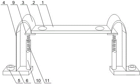
[0021] Such as figure 1 with figure 2 As shown, a kind of automobile radiator installation structure of the present invention, comprises fixed plate 1 and the support plate 4 that is arranged on the two ends of fixed plate 1, has mounting hole 2 on fixed plate 1, also includes elastic connector 3, and described elastic The connector 3 is U-shaped, and the opening of the U-shaped elastic connector 3 is downward. One end of the elastic connector 3 is connected to the end of the fixed plate 1, and the other end of the elastic connector 3 is connected to the upper end of the support plate 4. connection, the lower end of the support plate 4 is connected with a mount 6, and one end of the mount 6 has a fixing hole 7; it also includes a shock absorber 10 and a spring 11 placed in the shock absorber 10, and the shock absorber 10 is fixed On the mounting seat 5 , a connecting block 9 is installed at the bottom of the fixing plate 1 , and the two ends of the spring 11 are respectively...
Embodiment 2
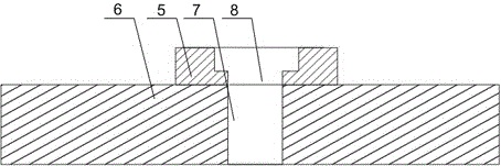
[0025] Such as figure 2 As shown, an automobile radiator installation structure of the present invention, an annular protrusion 5 is installed on the fixing hole 7, and the bottom of the annular protrusion 5 is provided with a through hole 8 communicating with the fixing hole 7, and the through hole 8 Isometric with fixing hole 7. The environment in the engine compartment is special, and sundries such as high temperature and oil stains are easy to accumulate, which has a great impact on the fixed connection of the mounting seat 6. Usually, the bolts are prone to corrosion and wire stripping. 5, and the bottom of the annular protrusion 5 is provided with a through hole 8 of equal diameter that communicates with the fixing hole 7, the screw rod passes through the through hole 8 and the fixing hole 7 to connect with the bottom of the machine compartment in turn, and the screw cover is fixed and protected in the ring In the groove, to prevent the screw and screw cover from being...
PUM
 Abstract
Description
Claims
Application Information
 - R&D Engineer
- R&D Manager
- IP Professional
- Industry Leading Data Capabilities
- Powerful AI technology
- Patent DNA Extraction
Browse by: Latest US Patents, China's latest patents, Technical Efficacy Thesaurus, Application Domain, Technology Topic, Popular Technical Reports.
© 2024 PatSnap. All rights reserved.Legal|Privacy policy|Modern Slavery Act Transparency Statement|Sitemap|About US| Contact US: help@patsnap.com