Air-conditioning apparatus
a technology for air conditioning and air conditioners, applied in lighting and heating apparatus, space heating and ventilation control systems, heating types, etc., to achieve the effect of efficient defrosting and quick star
- Summary
- Abstract
- Description
- Claims
- Application Information
AI Technical Summary
Benefits of technology
Problems solved by technology
Method used
Image

Examples
embodiment 1
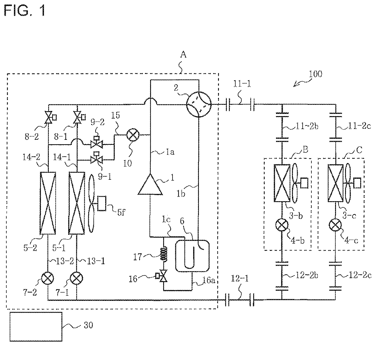
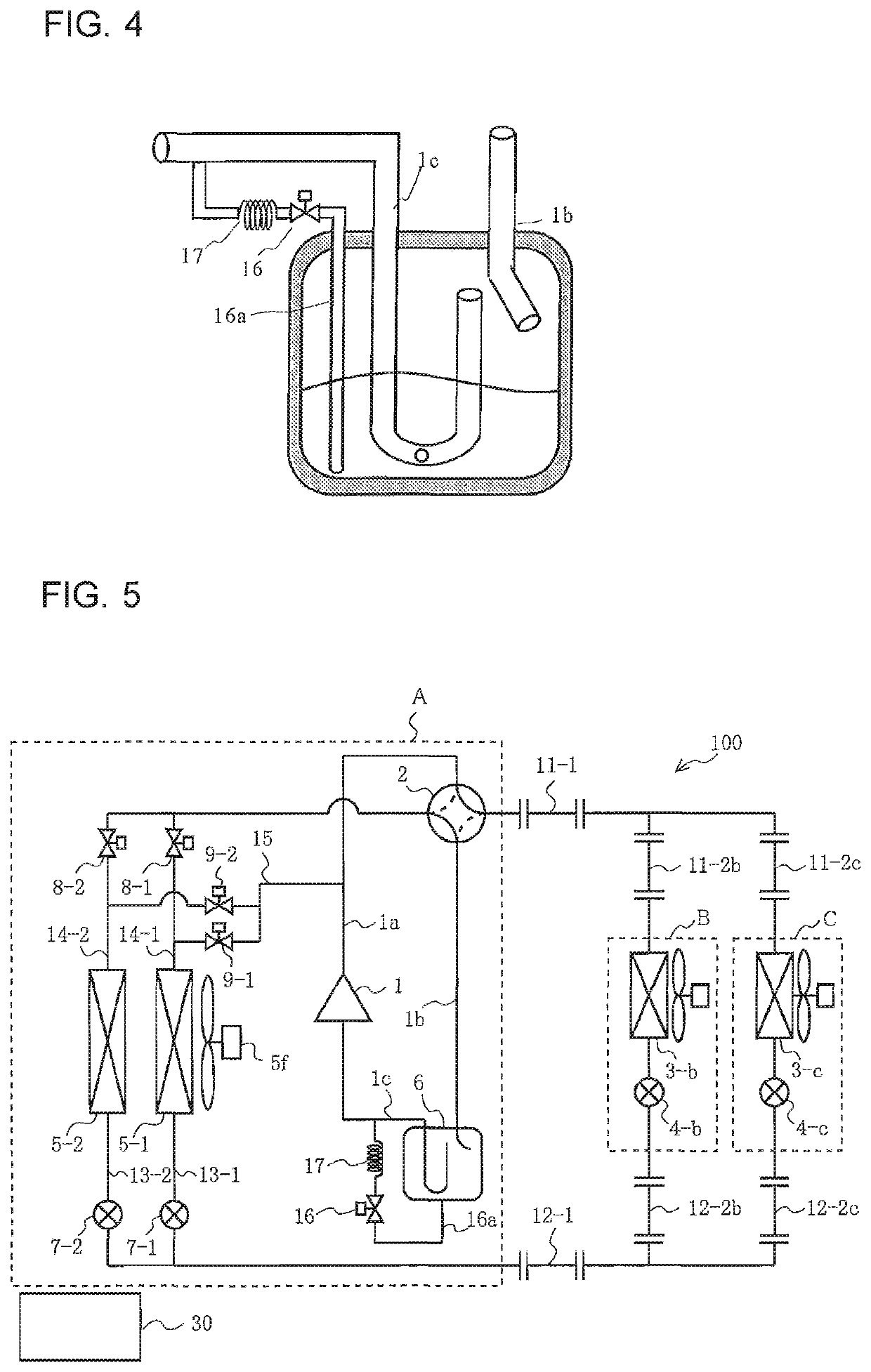
[0048]FIG. 1 is a refrigerant circuit diagram illustrating a configuration of a refrigerant circuit of an air-conditioning apparatus 100 according to Embodiment 1 of the present invention.
[0049]The air-conditioning apparatus 100 includes an outdoor unit A and a plurality of indoor units B and C connected in parallel with each other. The outdoor unit A and the indoor units B and C are connected to each other by first extension pipes 11-1, 11-2b, and 11-2c and second extension pipes 12-1, 12-2b, and 12-2c.
[0050]The air-conditioning apparatus 100 further includes a controller 30, which controls the cooling operation and the heating operation (normal heating operation, heating-defrosting operation) of the indoor units B and C.
[0051]The refrigerant used here is, for example, a fluorocarbon refrigerant, an HFO refrigerant, or a natural refrigerant. Examples of the fluorocarbon refrigerant include R32, R125, and R134a, which are HFC-based refrigerants, and R410A, R407c, and R404A, which a...
embodiment 2
[0184]FIG. 18 is a refrigerant circuit diagram illustrating a configuration of a refrigerant circuit of an air-conditioning apparatus 101 according to Embodiment 2 of the present invention.
[0185]The following description of the air-conditioning apparatus 101 will be focused on differences from Embodiment 1.
[0186]In addition to the components of the air-conditioning apparatus 100 according to Embodiment 1, the air-conditioning apparatus 101 of Embodiment 2 includes a second bypass pipe 18a connected to the discharge pipe 1a and the suction pipe 1b of the compressor. The second bypass pipe 18a is provided with a solenoid valve 18 and an expansion device 19. The solenoid valve 18 may be reduced in size to add a pressure loss to the refrigerant flowing through the solenoid valve, and then to remove the expansion device 19.
[0187]The solenoid valve 18 and the expansion device 19 in Embodiment 2 correspond to “second expansion device” of the present invention.
[0188]At the start of heating-...
embodiment 3
[0199]FIG. 21 is a refrigerant circuit diagram illustrating a configuration of a refrigerant circuit of an air-conditioning apparatus 102 according to Embodiment 3 of the present invention.
[0200]The following description of the air-conditioning apparatus 102 will be focused on differences from Embodiment 2.
[0201]Unlike the configuration of the air-conditioning apparatus 101 according to Embodiment 2, the first defrosting pipe 15 in the air-conditioning apparatus 102 of Embodiment 3 is connected to the first connection pipes 13-1 and 13-2.
[0202]At the same time, in addition to the components of the air-conditioning apparatus 100 according to Embodiment 1, the air-conditioning apparatus 102 includes a second defrosting pipe 22 that connects a pipe of a main circuit (between the second extension pipe 12-1 and the second flow control devices 7-1 and 7-2) to the second connection pipes 14-1 and 14-2.
[0203]The second defrosting pipe 22 is provided with a third flow control device 21, whic...
PUM
 Abstract
Description
Claims
Application Information
 - R&D
- Intellectual Property
- Life Sciences
- Materials
- Tech Scout
- Unparalleled Data Quality
- Higher Quality Content
- 60% Fewer Hallucinations
Browse by: Latest US Patents, China's latest patents, Technical Efficacy Thesaurus, Application Domain, Technology Topic, Popular Technical Reports.
© 2025 PatSnap. All rights reserved.Legal|Privacy policy|Modern Slavery Act Transparency Statement|Sitemap|About US| Contact US: help@patsnap.com