Phase shifter module, multiplexer/demultiplexer, and communication apparatus
a technology of phase shifter and module, applied in the field of phase shifter, can solve the problems of difficult matching, theoretically very difficult to achieve matching, and interference of saw filter with each other, and achieve the effect of reducing or preventing interferen
- Summary
- Abstract
- Description
- Claims
- Application Information
AI Technical Summary
Benefits of technology
Problems solved by technology
Method used
Image
Examples
first preferred embodiment
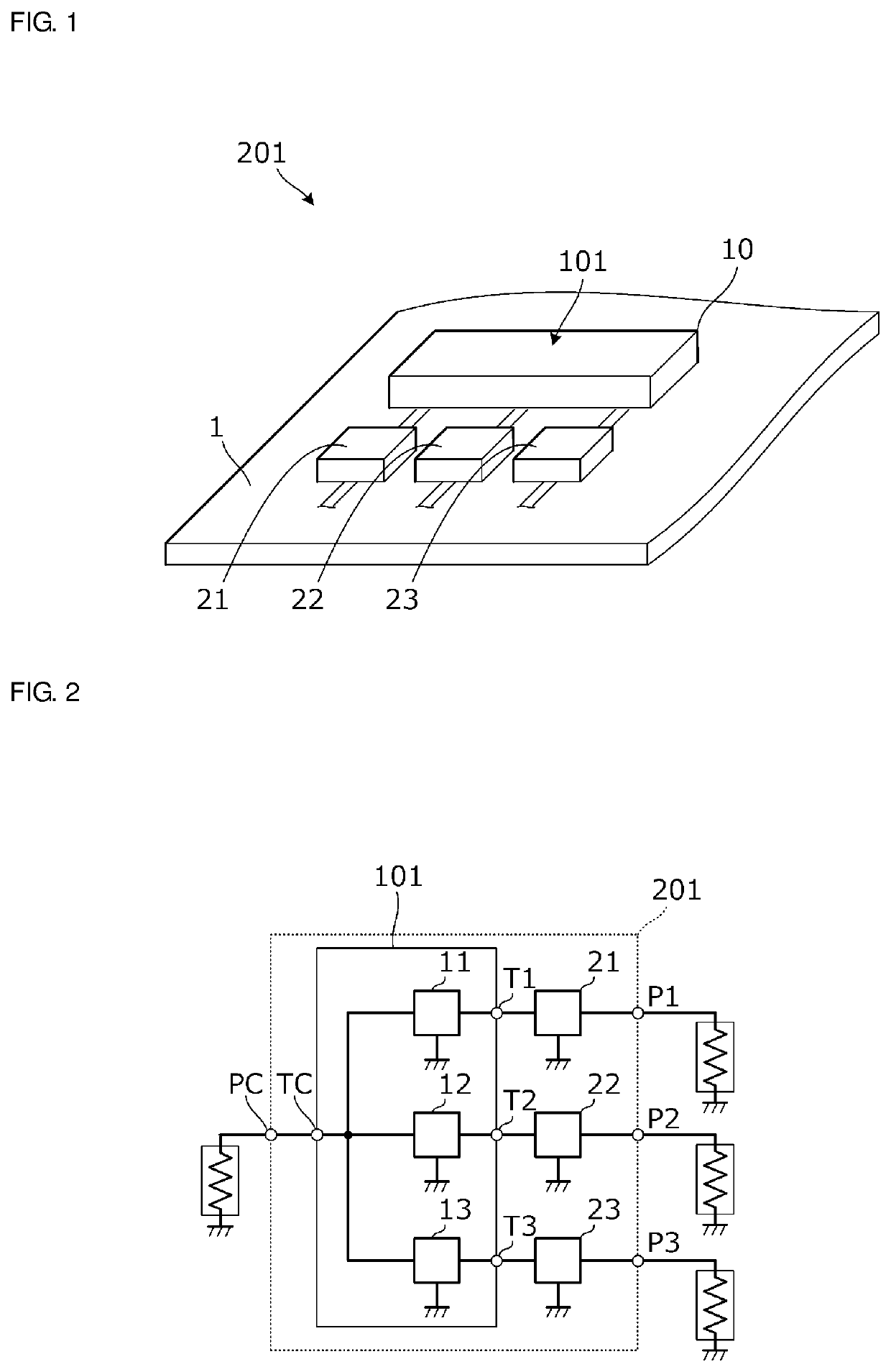
[0042]FIG. 1 is a perspective view of a phase shifter module according to a first preferred embodiment and a multiplexer / demultiplexer that includes the phase shifter module. A multiplexer / demultiplexer 201 according to this preferred embodiment includes a circuit substrate 1, SAW filters 21, 22, and 23, and a phase shifter module 101, and the SAW filters 21, 22, and 23 and the phase shifter module 101 are mounted on the circuit substrate 1. The phase shifter module 101 preferably includes three phase shifters, for example. The three phase shifters are provided at a base material 10.
[0043]FIG. 2 is a circuit diagram of a multiplexer / demultiplexer 201. The multiplexer / demultiplexer 201 includes a common port PC and individual ports P1, P2, and P3. Three phase shifters 11, 12, and 13 are connected between a common terminal TC and individual terminals T1, T2, and T3, respectively. The common terminal TC of the phase shifter module 101 is directly connected to the common port PC. The SA...
second preferred embodiment
[0070]In a second preferred embodiment of the present invention, an example of a multiplexer / demultiplexer structured as a single component will be described.
[0071]FIG. 8 is a perspective view of a multiplexer / demultiplexer 202. FIG. 9 is a front view of the multiplexer / demultiplexer 202 according to this preferred embodiment. In FIG. 9, the inside of the base material 10 is schematically illustrated. Furthermore, FIG. 10 is a circuit diagram of the multiplexer / demultiplexer 202. FIG. 10 is rendered taking into consideration the positional relationship of the phase shifters 11, 12, and 13 and the SAW filters 21, 22, and 23.
[0072]As illustrated in FIGS. 9 and 10, the phase shifters 11, 12, and 13 are provided inside the base material 10. On the upper surface of the base material 10, lands on which the SAW filters 21, 22, and 23 are to be mounted are provided. The individual terminals T1, T2, and T3 are part of the lands, and second terminals of the SAW filters 21, 22, and 23 are conn...
third preferred embodiment
[0075]In a third preferred embodiment of the present invention, an example of a communication apparatus that includes a multiplexer / demultiplexer will be described.
[0076]FIG. 11 is a circuit diagram of a communication apparatus 301. The communication apparatus 301 includes an antenna 211, a reception module 203, and communication circuits 221, 222, 223, 224, and 230. The reception module 203 includes a multiplexer / demultiplexer including a phase shifter module 103 and SAW filters 21, 22, 23, and 24. The communication circuits 221, 222, 223, and 224 are communication circuits for bands on a high band side, and the multiplexer / demultiplexer is connected between a high pass filter side of a diplexer 240 and the communication circuits 221, 222, 223, and 224. The communication circuit 230 is a communication circuit on a low band side and is connected to a low pass filter side of the diplexer 240.
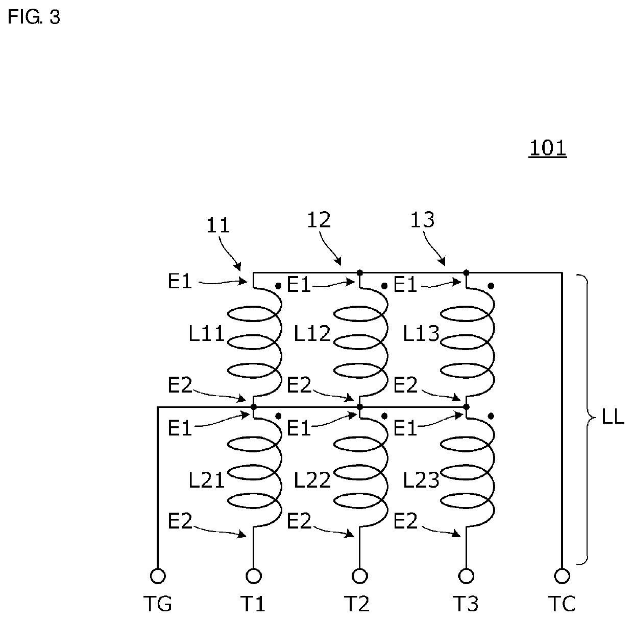
[0077]Structures of individual phase shifters in the phase shifter module 103 illustrated in ...
PUM
 Abstract
Description
Claims
Application Information
 - R&D
- Intellectual Property
- Life Sciences
- Materials
- Tech Scout
- Unparalleled Data Quality
- Higher Quality Content
- 60% Fewer Hallucinations
Browse by: Latest US Patents, China's latest patents, Technical Efficacy Thesaurus, Application Domain, Technology Topic, Popular Technical Reports.
© 2025 PatSnap. All rights reserved.Legal|Privacy policy|Modern Slavery Act Transparency Statement|Sitemap|About US| Contact US: help@patsnap.com


