
Work vehicle and method for controlling work vehicle

a technology for work vehicles and work trucks, applied in mechanical machines/dredgers, soil shifting machines/dredgers, transportation and packaging, etc., can solve the problems of compromising difficult to achieve both improved operability at low travel speed and linear stability at high travel speed, etc., to achieve the effect of improving operability at low speed and linear stability at high speed

Active Publication Date: 2020-08-04
KOMATSU LTD
View PDF31 Cites 3 Cited by
  • Summary
  • Abstract
  • Description
  • Claims
  • Application Information

AI Technical Summary

Benefits of technology

[0031]The present invention provides a work vehicle and a method for controlling a work vehicle with which operability at low speed and linear stability at high speed can be improved.

Problems solved by technology

With the work vehicles of the above-mentioned Japanese Laid-Open Patent Application H11-105723 and Japanese Patent Laid-Open Patent Application 11-321664, however, since the tactile sensation experienced by the operator is determined by the force required to change the open / close state of the port of the pilot valve, even though the speed of the work vehicle is changed, the tactile sensation of the joystick lever to the operator remains the same, which makes it difficult to achieve both improved operability at a low travel speed and linear stability at a high travel speed.
That is, if the tactile sensation is set to be light with an emphasis on improving operability during low-speed travel, linear stability at high speed will be compromised, and if the tactile sensation is set to be heavy with emphasis on linear stability at high speed, operability during low-speed travel will be compromised.

Method used


Image

  • Work vehicle and method for controlling work vehicle
  • Work vehicle and method for controlling work vehicle
  • Work vehicle and method for controlling work vehicle

Examples


embodiment 1

1. Configuration

1-1. Overview of Wheel Loader Configuration

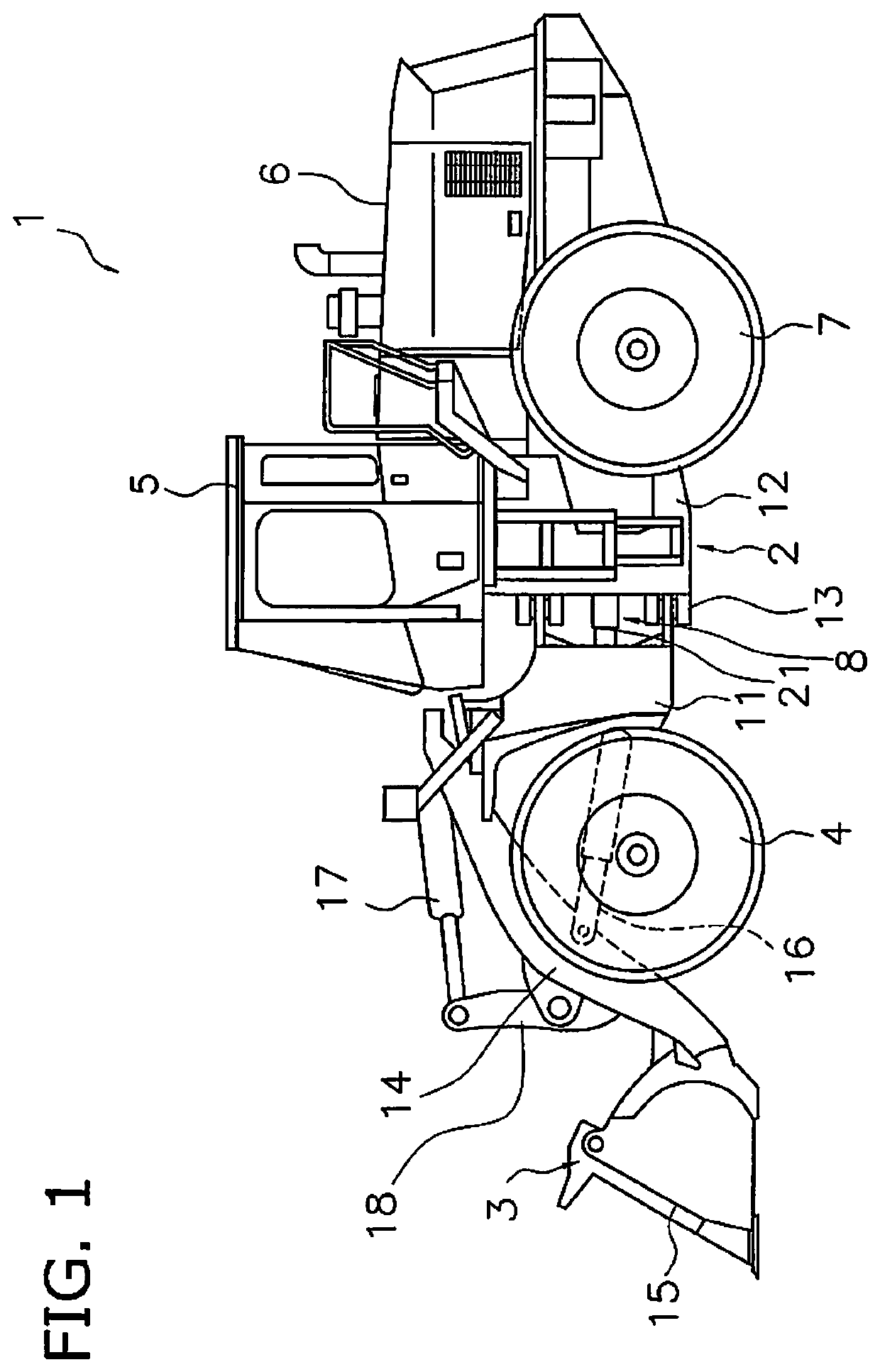
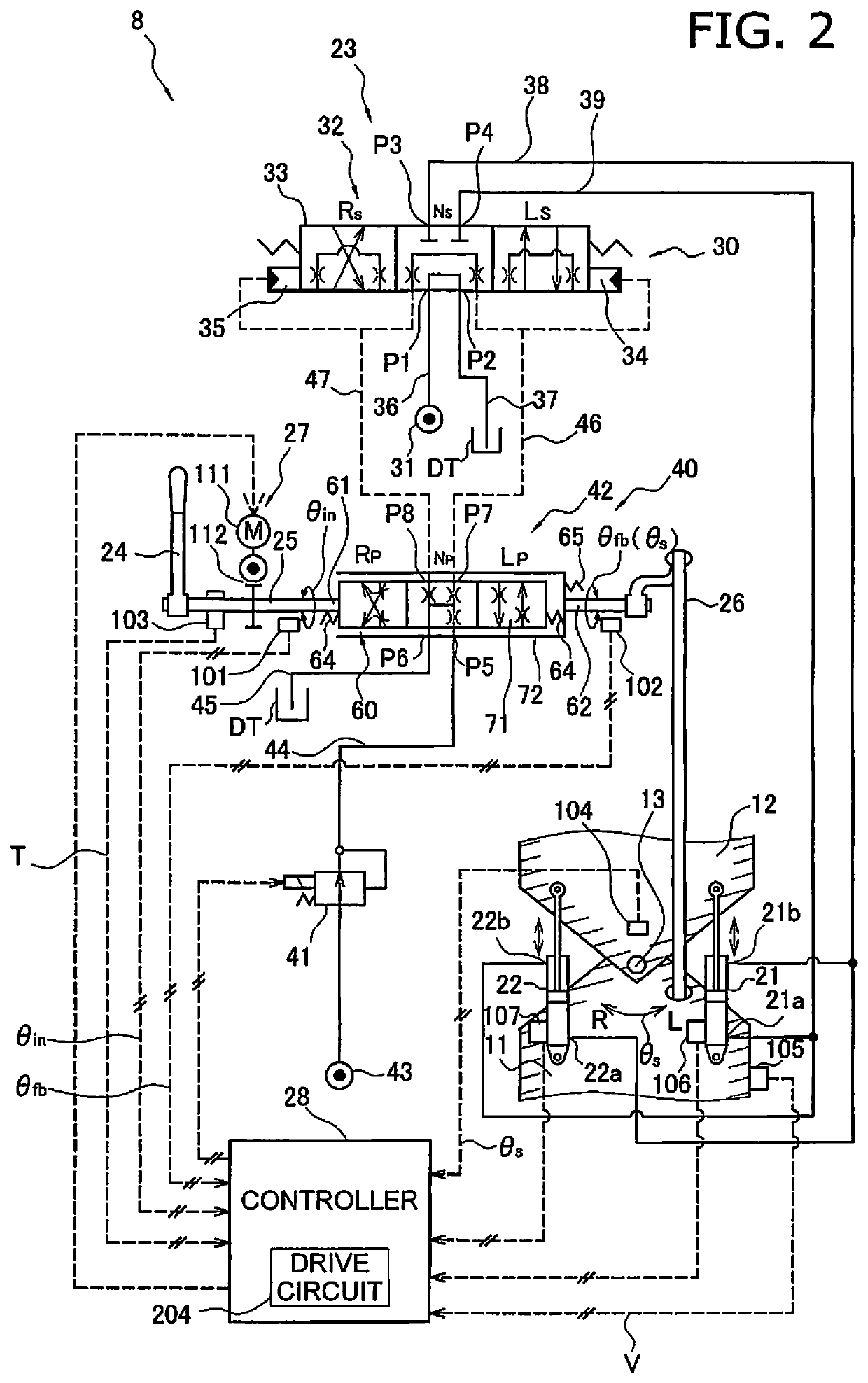
[0046]FIG. 1 is a simplified diagram of the configuration of a wheel loader 1 in this embodiment. The wheel loader 1 in this embodiment comprises a body frame 2, a work implement 3, a pair of front tires 4, a cab 5, an engine compartment 6, a pair of rear tires 7, and a steering operating device 8 (see FIG. 2, discussed below).

[0047]The wheel loader 1 performs earth loading and other such work with the work implement 3.

[0048]The body frame 2 is what is known as an articulated type, and has a front frame 11, a rear frame 12, and a linking shaft 13. The front frame 11 is disposed in front of the rear frame 12. The linking shaft 13 is provided in the center of the vehicle width direction, and pivotably links the front frame 11 to the rear frame 12. The front tires 4 are attached on the left and right sides of the front frame 11. The rear tires 7 are attached on the left and right sides of the rear frame 12.

[0049]The work implem...


PUM


Abstract

An articulated work vehicle with linked front and rear frames includes a joystick lever, a force imparting component, a speed sensor, and a controller. The joystick lever is configured to change a steering angle of the front frame with respect to the rear frame by operation by an operator. The force imparting component is configured to impart an assist force or a counterforce to operation of the joystick lever by the operator. The speed sensor is configured to sense speed of the work vehicle. The controller is configured to control the force imparting component so as to impart the assist force or the counterforce according to the speed sensed by the speed sensor.

Description

CROSS-REFERENCE TO RELATED APPLICATIONS[0001]This application is a U.S. National stage application of International Application No. PCT / JP2016 / 081730, filed on Oct. 26, 2016. This U.S. National stage application claims priority under 35 U.S.C. § 119(a) to Japanese Patent Application No. 2015-213789, filed in Japan on Oct. 30, 2015, the entire contents of which are hereby incorporated herein by reference.BACKGROUNDField of the Invention[0002]The present invention relates to a work vehicle and a method for controlling a work vehicle.Description of the Related Art[0003]An articulated work vehicle has been disclosed with a configuration in which the steering angle is changed by controlling the flow of fluid supplied to a hydraulic actuator disposed from the front frame to the rear frame (see Japanese Laid-Open Patent Application H11-105723 and Japanese Patent Laid-Open Patent Application 11-321664, for example).[0004]With the work vehicles in Japanese Laid-Open Patent Application H11-10...

Claims


Application Information

Patent Timeline
Patent Type & Authority Patents(United States)
IPC IPC(8): B62D6/00E02F9/22E02F9/20E02F3/28E02F9/08B62D12/00B62D6/02B62D5/083B62D5/09B62D5/00B62D1/12
CPCB62D5/091E02F9/0841B62D5/006E02F9/2004E02F9/225B62D6/008B62D12/00B62D6/02B62D1/12B62D5/0832E02F3/283
Inventor TAKENAKA, YUITANAKABAYASHI, MASANOBUIKARI, MASANORI
Owner KOMATSU LTD
Learn More