
Stealth firearm safety and trigger lock system

a technology of trigger lock and firearm safety, applied in the field of firearms, can solve the problems of unauthorized use of weapons by older children and others, significant harm and loss of life to others, and cannot prevent unauthorized users from taking and firing weapons

Active Publication Date: 2020-07-28
STANLEY J D
View PDF8 Cites 3 Cited by
  • Summary
  • Abstract
  • Description
  • Claims
  • Application Information

AI Technical Summary

Benefits of technology

The device described in this patent is a safety switch for firearms that prevents the weapon from being fired if it is accidentally triggered. The switch has two rotating parts that lock together to prevent movement of the trigger mechanism. The device can be added as a retrofit to an existing safety switch or used in conjunction with an existing switch that uses a rotating part to block or allow trigger movement. The secondary rotating part is designed to appear stealth and is hidden behind a cover to prevent accidental triggering. This makes the device safer and more effective in preventing accidents.

Problems solved by technology

While such a safety switch mechanism is in widespread use in firearms and works well to prevent the owner or authorized user of the weapon, it does not prevent unauthorized users from taking and firing the weapon since a simple rotation of the safety will place the firearm in the firing position.
Additionally, where the firearm is stolen or taken from the owner by an individual familiar with trigger safety mechanisms, it may be used against the owner.
As a consequence, while conventional trigger safety switches employed with modern firearms work well in many instances, they do not prevent the unauthorized use of the weapon by older children and others coming into possession of it.
The consequences of such can be significant harm and loss of life to others encountering the individual who has such unauthorized possession of the firearm.
Various other limitations of the related art are known or will become apparent to those skilled in the art upon a reading and understanding of the specification below and the accompanying drawings.

Method used


Image

  • Stealth firearm safety and trigger lock system
  • Stealth firearm safety and trigger lock system
  • Stealth firearm safety and trigger lock system

Examples


Embodiment Construction

[0036]In this description, the directional prepositions of up, upwardly, down, downwardly, front, back, top, upper, bottom, lower, left, right and other such terms refer to the device as it is oriented and appears in the drawings and are used for convenience only and such are not intended to be limiting or to imply that the device has to be used or positioned in any particular orientation.

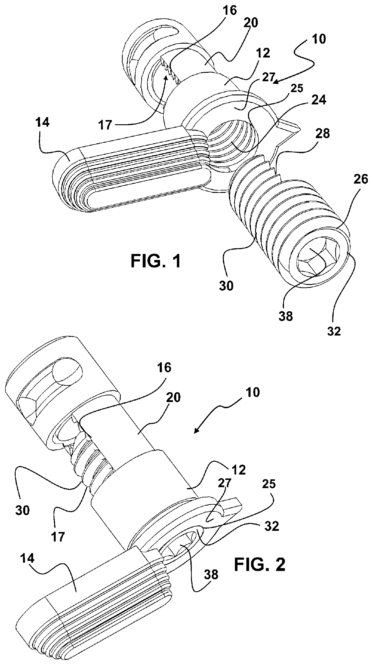
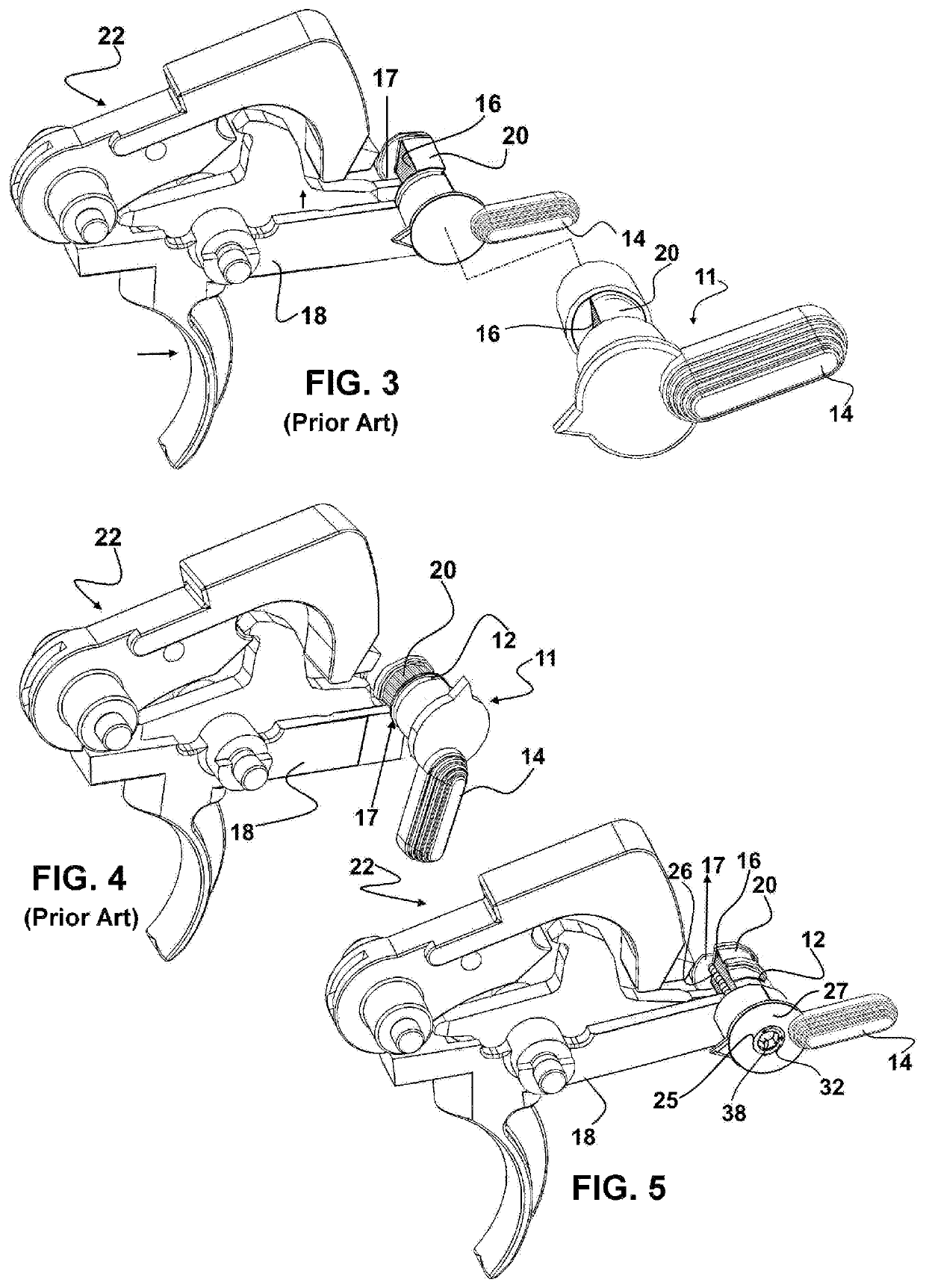
[0037]Now referring to drawings in FIGS. 1-10, wherein similar components are identified by like reference numerals, there is seen in FIG. 1, an exploded view of the components of the a preferred mode of the trigger safety and locking device 10 herein.

[0038]As shown, the device 10 in all modes employs a first rotating member 12 which may be provided by the OEM factory installed trigger safety which is constructed with such a first rotating member 12, or which may be provide by the device 10 herein in a retrofit mode, to replace the factory installed safety having a solid core rotating member. In al...


PUM


Abstract

A secondary trigger safety is provided in a trigger mechanism which employs first rotating member which is rotatable between a safety on position preventing firing and a safety off position enabling trigger firing. The secondary trigger safety is coaxially positioned within a formed axial passage in the first rotating member. To position the trigger in the safety off position to allow firing, both the first rotating member and the second rotating member must be turned to respective positions aligning a passage in the first rotating member with a recess in the second rotating member.

Description

FIELD OF THE INVENTION[0001]The disclosed device concerns firearms. More particularly, it relates to a device and method for securing firearms against unintentional and unauthorized use through the provision of a stealth coaxial trigger safety and trigger lock system.BACKGROUND OF THE INVENTION[0002]Firearms in the modern era conventionally employ a bullet or shell which is positioned within the firearm and has both propellent and the projectile in a single unit. Once operatively positioned within a firearm, a trigger mechanism either in a single action or double action, causes the actuation of a hammer or firing pin which strikes the bullet or shell to cause it to discharge and propel the projectile from the barrel of the firearm toward an intended target.[0003]Because of the ease of activating the trigger of many modern firearms, conventionally they are also equipped with a trigger safety mechanism or switch. Such trigger safety switches generally have two primary positions. A fir...

Claims


Application Information

Patent Timeline
IPC IPC(8): F41A17/46
CPCF41A17/46F41A17/02
Inventor STANLEY, J. D.
Owner STANLEY J D
Learn More