Device for motion transmission on cycles
a technology of motion transmission and cycle, which is applied in the direction of transportation and packaging, hoisting equipment, couplings, etc., can solve the problems of loosening the adjustment and of the various mechanical components, affecting the smoothness of the cycle, and causing the cycle to be more tiring
Active Publication Date: 2020-06-02
METALSISTEM
View PDF21 Cites 0 Cited by
- Summary
- Abstract
- Description
- Claims
- Application Information
AI Technical Summary
Benefits of technology
The main purpose of this patent is to create a device that makes it easier to change gear ratios and minimize friction in bicycles. Prior to this invention, many devices were complicated and expensive, but this device is simple and effective.
Problems solved by technology
The transmission systems of known type have various drawbacks related to the fact that the chain undergoes continuous inclination during the travel, both to switch from one gear ratio to another, and to maintain the same gear ratio, while the rotation axes of the cogwheels remain fixed
Consequently, the non perfect alignment between chain and cogwheels, dissipates part of the energy generated by the cyclist by producing friction, making his / her pedaling more tiring.
In the long run, also, the frequent inclinations cause a loosening of the adjustments and of the various mechanical components of the system, with consequent problems related to the operation of the system such as, e.g., unwanted shifts of the chain, unwanted shifts from one wheel to another, wear due to incorrect positioning of the chain, etc
Furthermore, the chain, following its inclination, produces a friction on the cogwheels and can deform or otherwise wear out the parts of the system (both cogwheels and the chain).
This leads to an inclination of the axis of rotation of the cranksets with respect to the axis of rotation of the wheel, with consequent malfunction which can cause problems during the normal course of the race.
Method used
View moreImage
Smart ImageViewing Examples
Examples
first embodiment
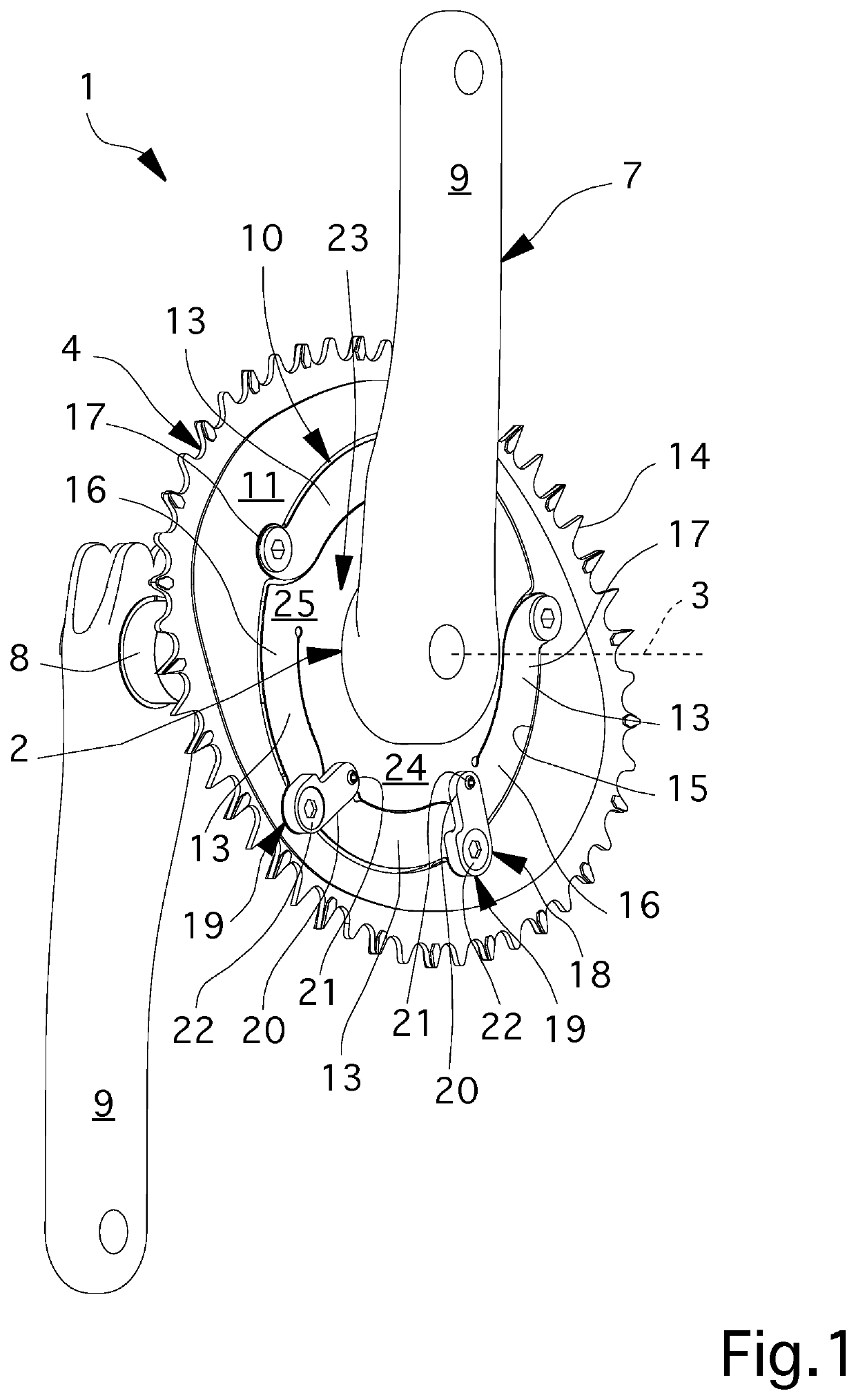
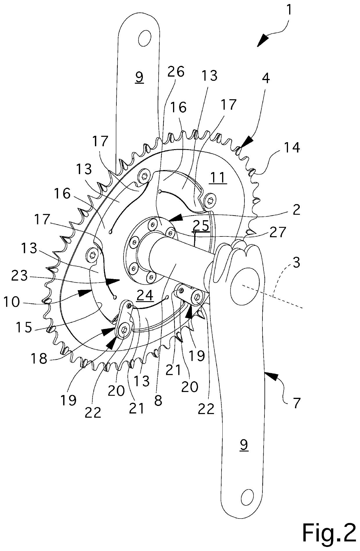
[0024]FIGS. 1 and 2 are an axonometric view of the device according to the invention;
second embodiment
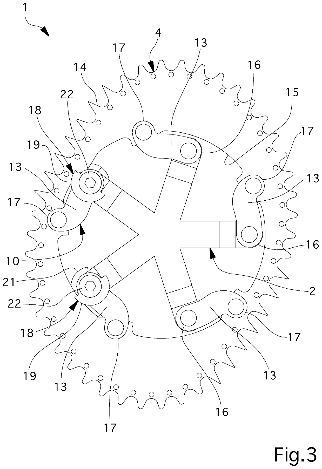
[0025]FIG. 3 is a side view of the device according to the invention;
[0026]FIGS. 4 and 5 are a schematic view of the device according to the invention in two different work configurations.
Login to View More PUM
 Abstract
The device for the motion transmission onto cycles comprises:a connecting core able to be associated with a frame of a cycle in a rotatable way around an axis of rotation; anda ring gear lying on a lying plane surrounding the core and able to be coupled to a flexible transmission element closed on itself in a loop for starting said cycle along a direction of forward movement;oscillation means placed between the connecting core and the ring gear and able to tilt the lying plane with respect to the axis of rotation.
Description
CROSS REFERENCE TO RELATED APPLICATION(S)[0001]This application is a U.S. National Stage Entry of International Patent Application No. PCT / IB2016 / 053625, filed Jun. 17, 2016, which claims the benefit of Italian Patent Application No. 102015000046386, filed Aug. 25, 2015, the disclosures of which are hereby incorporated entirely herein by reference.BACKGROUNDTechnical Field[0002]The present invention relates to a device for the motion transmission onto cycles.Background Art[0003]In the present treatise, the word “cycles” means vehicles with two or more wheels functioning exclusively by muscular propulsion, by means of pedals or similar devices, operated by people on the vehicle.[0004]Also considered as cycles are bicycles with pedal assistance, equipped with an auxiliary electric motor the output of which is progressively reduced and finally cut off when the vehicle reaches a predetermined speed or sooner, if the cyclist stops pedaling[0005]The transmission systems commonly used in b...
Claims
Login to View More Application Information
Patent Timeline
 Patent Type & Authority Patents(United States)
IPC IPC(8): B62M9/10F16D3/60F16D3/02F16H55/14B62M9/12F16H55/30
CPCB62M9/105B62M9/12F16H55/14F16H55/30F16D3/02F16D3/60B62M9/16
Inventor BRIOSI, ANTONELLO
Owner METALSISTEM
Features
- R&D
- Intellectual Property
- Life Sciences
- Materials
- Tech Scout
- Unparalleled Data Quality
- Higher Quality Content
- 60% Fewer Hallucinations
Learn More Browse by: Latest US Patents, China's latest patents, Technical Efficacy Thesaurus, Application Domain, Technology Topic, Popular Technical Reports.
© 2025 PatSnap. All rights reserved.Legal|Privacy policy|Modern Slavery Act Transparency Statement|Sitemap|About US| Contact US: help@patsnap.com


