Gear machining method and gear machining device
a gear machining and gear technology, applied in the direction of gear teeth, gear-teeth manufacturing apparatus, manufacturing tools, etc., can solve the problems increasing the period of time required for gear machining, and difficult manufacturing of tools, so as to reduce the cost of tools, improve machining accuracy, and suppress the effect of increasing the cost of tools
- Summary
- Abstract
- Description
- Claims
- Application Information
AI Technical Summary
Benefits of technology
Problems solved by technology
Method used
Image

Examples
first embodiment
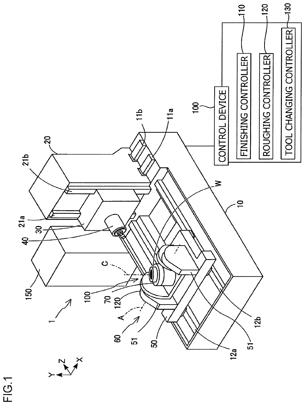
[0027]Embodiments according to a gear machining method of the present invention are described below with reference to the drawings. The following describes first an overall structure of a gear machining device 1 used in a gear machining method according to the present invention with reference to FIG. 1.
[0028]As depicted in FIG. 1, the gear machining device 1 is a machining center having three linear axes (X-axis, Y-axis, and Z-axis) orthogonal to each other and two rotational axes (A-axis and C-axis) as drive axes, and performs relative feeding operation between a workpiece W and a tool. The gear machining device 1 may be a horizontal machining center, a vertical machining center, or a complex processing machine. The gear machining device 1 mainly includes a bed 10, a column 20, a saddle 30, a rotary main spindle 40, a table 50, a tilt table 60, a turntable 70, a tool changer 150, and a control device 100.
[0029]The bed 10 is disposed on a floor. The column 20 is disposed on an upper...
second embodiment
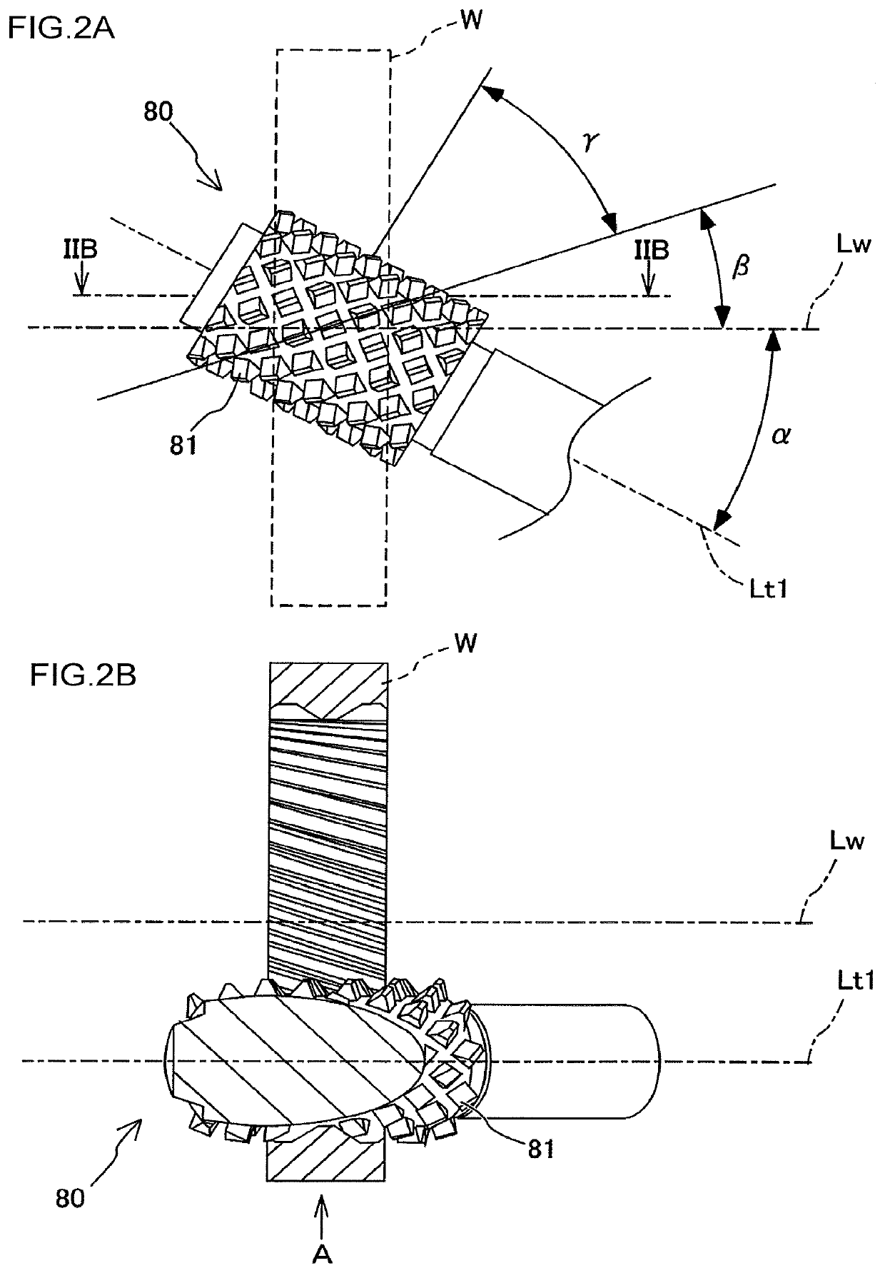
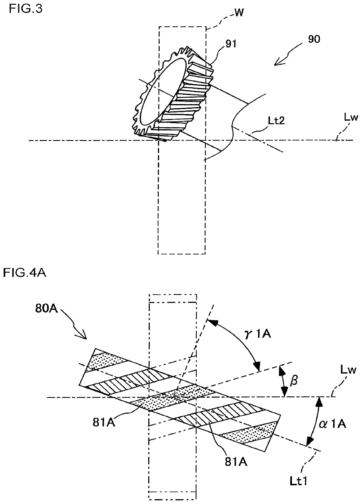
[0060]As depicted in FIG. 5A and FIG. 5B, in a gear machining method at the roughing step using the hob cutter 80, the gear machining device 1 first disposes the hob cutter 80 such that a setting angle matches the helix angle of a helical gear to be formed on the workpiece W and the thread angle of the hob cutter 80. Subsequently, the gear machining device 1 moves the hob cutter 80 in the radial direction to dispose the hob cutter 80 at a position that enables machining of the workpiece W. The gear machining device 1 machines an inner peripheral surface of the workpiece W while maintaining the position of the hob cutter 80 in the rotation axis Lt1 direction with respect to the workpiece W. After the roughing step is completed, the gear machining device 1 performs finishing by cutting off, with a skiving cutter 90, a cutting allowance remaining on the workpiece W so as to form a desired gear shape.
[0061]In the gear machining method of the present embodiment, gear machining is perfor...
third embodiment
[0071]The following describes modifications when external teeth is formed on a workpiece W. In the third embodiment described above, the helical direction of hob blades 81 formed on a hob cutter 80 is the same as the helical direction of a helical gear to be formed on a workpiece W. However, the present invention is not limited to this. Specifically, the helical direction of the hob blades 81 formed on the hob cutter 80 may be opposite to the helical direction of the helical gear to be formed on the workpiece W.
[0072]In this case, when the same pitch is used and the setting angle is set to a positive value, the setting angle increases as the thread angle of the hob blades 81 decreases. In other words, the setting angle can be set larger for a hob cutter 80 having single-thread hob blades 81 than for a hob cutter 80 having multi-thread hob blades 81.
[0073]The embodiments above describes cases in which the present invention is applied when a helical gear is formed on a workpiece W. Ho...
PUM
| Property | Measurement | Unit |
|---|---|---|
| thread angle γ1A | aaaaa | aaaaa |
| thread angle γ1B | aaaaa | aaaaa |
| setting angle | aaaaa | aaaaa |
Abstract
Description
Claims
Application Information
 - R&D
- Intellectual Property
- Life Sciences
- Materials
- Tech Scout
- Unparalleled Data Quality
- Higher Quality Content
- 60% Fewer Hallucinations
Browse by: Latest US Patents, China's latest patents, Technical Efficacy Thesaurus, Application Domain, Technology Topic, Popular Technical Reports.
© 2025 PatSnap. All rights reserved.Legal|Privacy policy|Modern Slavery Act Transparency Statement|Sitemap|About US| Contact US: help@patsnap.com