
Spot welded joint and spot welding method

a spot welding and joint technology, applied in welding/soldering/cutting articles, manufacturing tools, transportation and packaging, etc., can solve the problems of fracture toughness of the weld falling, the strength of the welded joint becomes an issue, and the weld is easily hardened, so as to achieve highly reliable spot welding and remarkable raised toughness. , the effect of spot welding

Active Publication Date: 2020-05-12
NIPPON STEEL CORP
View PDF25 Cites 0 Cited by
  • Summary
  • Abstract
  • Description
  • Claims
  • Application Information

AI Technical Summary

Benefits of technology

The present invention improves the strength of spot welds, resulting in a more reliable joint.

Problems solved by technology

In spot welding of high strength steel sheets, the strength of the welded joint becomes an issue.
Further, due to the increase in the alloy elements, the weld is easily hardened and the fracture toughness of the weld falls.
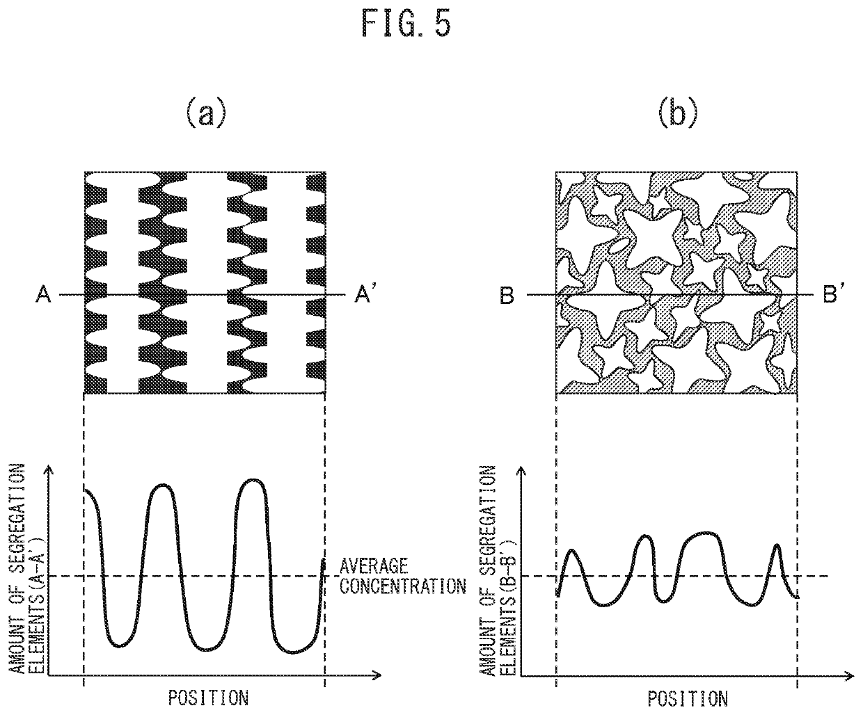
In this method, the re-conduction eases the segregation, but the solidified structures are not refined.
As a result, a sufficient fracture toughness cannot be obtained.
Further, repetition of re-conduction and hold are necessary, so a long time is required for welding and the advantage of spot welding of the short welding time cannot be enjoyed.
In this method, the martensite transformation is substantially completed before the operation of running current for tempering, so a long cooling time becomes necessary and there was the problem that the advantage of spot welding of the short welding time cannot be enjoyed.
In this method, a separate step becomes required after welding and the work procedure becomes complicated.
In this method, the steel sheets which can be used are limited.
Further, a long time is required for welding, so the productivity is low.
With just this provision, it is not possible to obtain a highly reliable joint strength.

Method used


Image

  • Spot welded joint and spot welding method
  • Spot welded joint and spot welding method
  • Spot welded joint and spot welding method

Examples


example 1

[0080]The steel sheets shown in Table 1 were prepared and spot welded by the combinations shown in Table 2. The welding conditions are shown together in Table 2.

[0081]

TABLE 1SheetType ofStrengthAmount of CCarbonthicknessNo.steel sheet(MPa)(mass %)equivalent(mm)1Cold rolled9800.130.2322Cold rolled11800.190.411.23Zinc plated9800.130.231.64Hot stamped14700.220.341.6

[0082]Here, “carbon equivalent” is the value found by the following formula using the contents (mass %) of C, Si, Mn, P, and S.

Carbon equivalent=C (mass %)+Si (mass %) / 30+Mn (mass %) / 20+P (mass %)×4+S (mass %)×4

[0083]In Table 2, “A” is the value found by A=νS / (λD·fV) where the frequency of the electromagnetic vibration in the solidification step is fV, the solidification speed is νS, and the arm interval of dendrites is λD. For the solidification speed and arm interval of dendrites, the values experimentally found in advance as explained above using the combination of sheets and types of steel used were used.

[0084]

TABLE 2Con...


PUM

PropertyMeasurementUnit
tensile strengthaaaaaaaaaa

Abstract

The present invention has as its object to provide a spot welded joint and spot welding method which raise the fracture toughness of spot welded metal to raise the strength of the spot welded joint. In the present invention, there is provided a spot welding method comprising a melt zone forming step forming a melt zone by conduction and, after the melt zone forming step, a solidification step of running a current lower than the current run in the melt zone forming step so as to cause the melt zone to solidify, wherein, in the solidification step, electromagnetic vibration is applied to the melt zone, and a frequency fV of the electromagnetic vibration, a solidification speed νS when the melt zone solidifies, and an arm interval of dendrites λD when the melt zone solidifies satisfy 0.2≤νS / (λD·fV)≤4.0.

Description

TECHNICAL FIELD[0001]The present invention relates to a welding method comprising superposing and spot welding tensile strength 750 to 2500 MPa high strength steel sheets used in the automobile field etc., in particular tensile strength 980 MPa or more high strength steel sheets, and a spot welded joint formed by that welding method.BACKGROUND ART[0002]In recent years, in the automotive field, car bodies have been reduced in weight to reduce fuel consumption and cut CO2 emissions and have been improved in collision safety by use of high strength steel sheet for the car bodies and their parts. For assembly of car bodies and attachment of parts etc., spot welding is mainly being used. In spot welding of high strength steel sheets, the strength of the welded joint becomes an issue.[0003]In a joint formed by superposing and spot welding steel sheets (below referred to as a “spot welded joint”), the tensile strength is an important characteristic. Normally, the mechanical characteristics...

Claims


Application Information

Patent Timeline
Patent Type & Authority Patents(United States)
IPC IPC(8): B23K11/11B23K11/16B23K11/12B23K101/00B23K103/04
CPCB23K11/11B23K11/12B23K11/16B23K2101/006B23K2103/04B23K11/10
Inventor WATANABE, FUMINORIMIYAZAKI, YASUNOBU
Owner NIPPON STEEL CORP
Learn More