
Checking fixture

a technology of checking fixture and milling machine, which is applied in the direction of mechanical measuring arrangement, manufacturing tools, instruments, etc., can solve the problems of unnecessarily complicated milling machine, relatively expensive milling machine, and relatively long time for manufacturing a checking fixture using a milling machin

Active Publication Date: 2020-04-21
VOLVO CAR CORP
View PDF17 Cites 1 Cited by
  • Summary
  • Abstract
  • Description
  • Claims
  • Application Information

AI Technical Summary

Benefits of technology

[0006]In view of above, it is an object of the present invention to provide a checking fixture which may be produced by simple means. In particular, an object of the invention is to provide a checking fixture which can be produced without the need for a milling machine.
[0008]The present invention is based on the realization that by using laser cutting for producing parts of the checking fixtures a simpler way of manufacturing a checking fixture is provided. By the provision of using laser cutting, a metallic support sheet may be produced with defined holes for the placement of holder members. The metallic support sheet produced by laser cutting provides a versatile platform for attaching the holder members without the need for complicated and expensive milling techniques. Furthermore, the metallic sheet reinforcement structure advantageously produced by laser cutting provides reinforcement for the holder members such that their relative positions are maintained, thus providing stabilized holder members for holding e.g. the vehicle component holders and measurement devices.
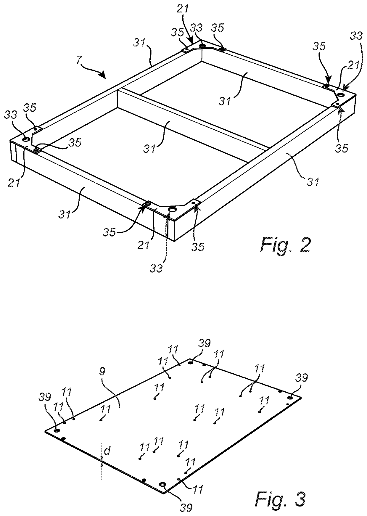
[0014]The bottom support frame may comprise a plurality of metallic beams which are welded together to form the frame. The main function of the bottom frame is to support the weight of the checking fixture and to provide a stable support.
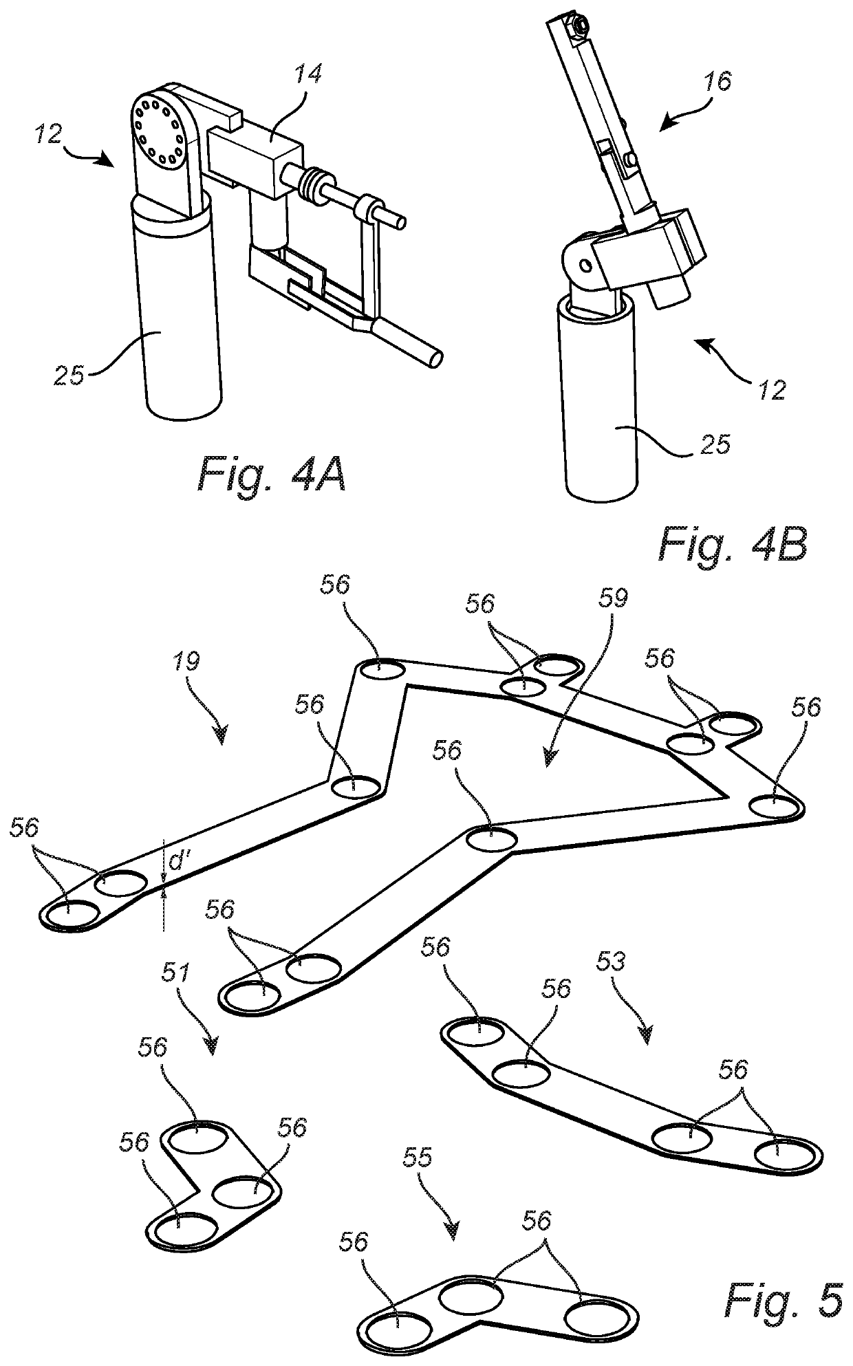
[0015]Furthermore, the metallic sheet reinforcement structure may be welded to the holder members. Hereby, a stronger reinforcement for maintaining the relative position of the holder members is provided compared to e.g. bolting or gluing etc.

Problems solved by technology

However, using milling requires relatively expensive and unnecessarily complicated milling machines.
Furthermore, the lead time for manufacturing a checking fixture using a milling machine tends to be relatively long.

Method used


Image

  • Checking fixture
  • Checking fixture
  • Checking fixture

Examples


Embodiment Construction

[0035]This invention may be embodied in many different forms and should not be construed as limited to the embodiments set forth herein; rather, these embodiments are provided for thoroughness and completeness, and fully convey the scope of the invention to the skilled person. Like reference characters refer to like elements throughout.

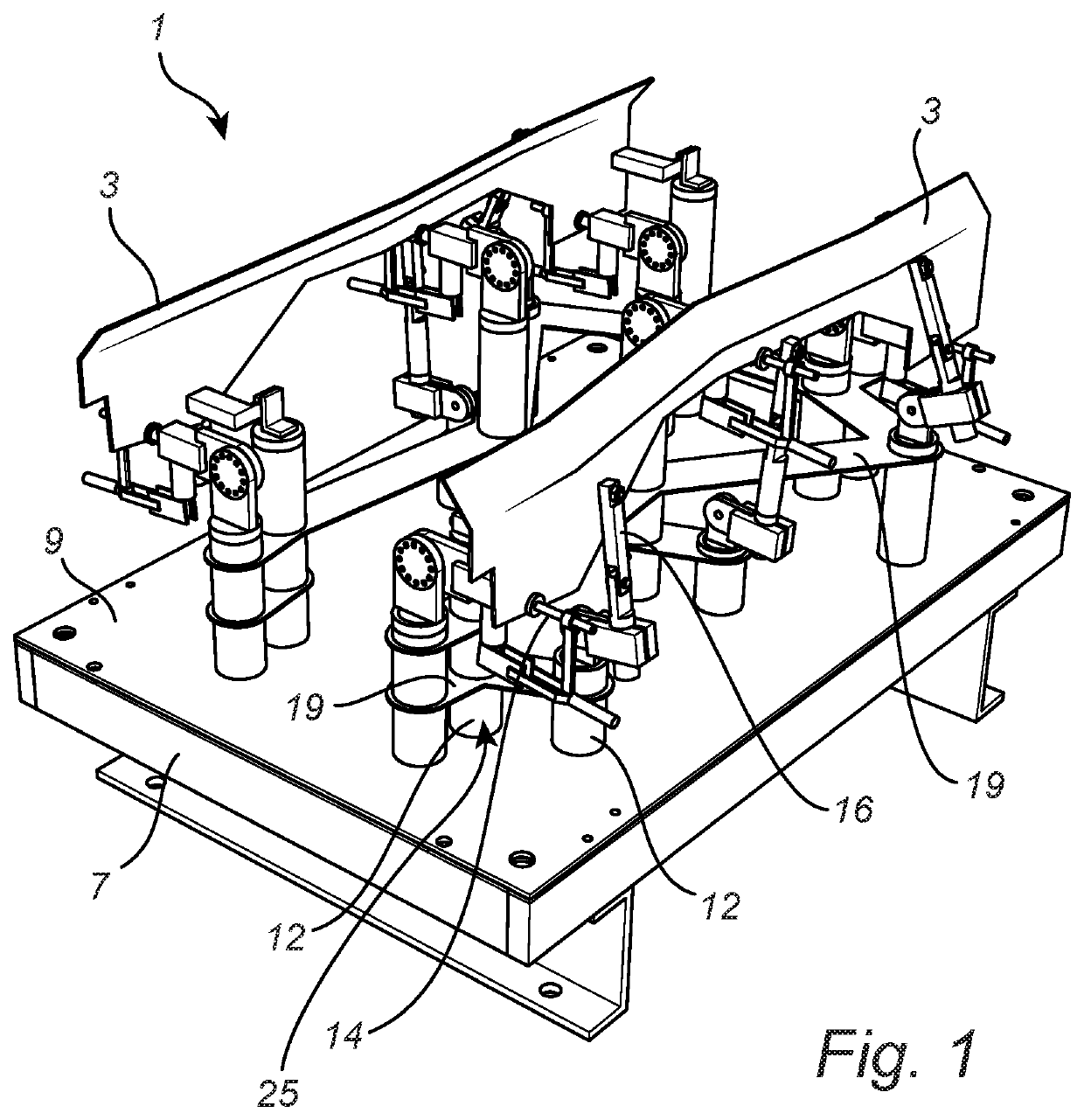
[0036]FIG. 1 shows an exemplary checking fixture 1 according to embodiments of the invention. The checking fixture 1 is shown to hold vehicle components 3 in the form of a metallic component for the vehicle. It should be noted that a wide variety of vehicle components (armrests, vehicle frame parts, beams, seat parts, bumpers, lights, etc.) may be inspected in a checking fixture, such as metallic or plastic sheet articles, and even fabric articles for the vehicle. The vehicle components 3 in FIG. 1 are exemplified by a metallic frame part 3. The vehicle components 3 are held in place by a plurality of vehicle component holders in the form of clamping ...


PUM

PropertyMeasurementUnit
thicknessaaaaaaaaaa
thicknessaaaaaaaaaa
thicknessaaaaaaaaaa

Abstract

The present invention relates to a checking fixture comprising: a bottom support frame; a metallic support sheet mechanically fixated to the bottom support frame, the metallic support sheet comprising a plurality of through holes arranged in a predetermined layout; a plurality of holder members for holding vehicle component holders or vehicle component measurement devices, the holder members being attached to the metallic support sheet in the through holes and being adapted to extend away from an upper surface of the metallic support sheet; at least one metallic sheet reinforcement structure arranged orthogonally separated from the metallic support sheet, the metallic sheet reinforcement structure being adapted to fixate the relative position of at least two of the holders members. The metallic support sheet and the metallic reinforcement sheet structure are made from laser cut sheet material.

Description

CROSS-REFERENCE TO RELATED APPLICATION[0001]This application claims priority under 35 U.S.C. § 119 based on European Patent Application No. 17161094.2, filed Mar. 15, 2017, the disclosure of which is hereby incorporated by reference herein.FIELD OF THE INVENTION[0002]The present invention relates to a checking fixture for inspecting vehicle components and to a method for manufacturing such a checking fixture.BACKGROUND OF THE INVENTION[0003]Checking fixtures in the automotive industry are generally used for inspecting the shape and measures of vehicle components. Checking fixtures are particularly useful for inspecting vehicle components having complex shapes. For a vehicle component inspection, the vehicle component is fixated in the checking fixture by holders arranged at specific locations in the checking fixture. Once the vehicle component is fixated, measurement devices are used for determining measures in predetermined directions and locations of the vehicle component.[0004]Ch...

Claims


Application Information

Patent Timeline
Patent Type & Authority Patents(United States)
IPC IPC(8): B62D65/00B23K26/40G01B5/207B23K31/02G01B5/00B23K26/38B23K101/20B23K101/24B23K103/04
CPCG01B5/0025B23K26/40G01B5/207G01B5/0004B23K31/02B62D65/005B23K26/38B23K2103/04B23K2103/05B60Y2304/09B23K2101/24B23K2101/20B23K26/702
Inventor STANGGREN, ULF
Owner VOLVO CAR CORP
Learn More