
Quantum dot light emitting devices (QLEDs) and method of manufacture

a light-emitting device and quantum dot technology, applied in the direction of basic electric elements, semiconductor devices, electrical equipment, etc., can solve the problems of limiting the penetration of quantum dot light-emitting devices into practical clinical use, the electroluminescence properties of quantum dot devices remain inferior to organic light-emitting, etc., to achieve small efficiency roll-off, high peak current efficiency, and high driving current density

Active Publication Date: 2020-03-17
UNIV OF CENT FLORIDA RES FOUND INC
View PDF12 Cites 3 Cited by
  • Summary
  • Abstract
  • Description
  • Claims
  • Application Information

AI Technical Summary

Benefits of technology

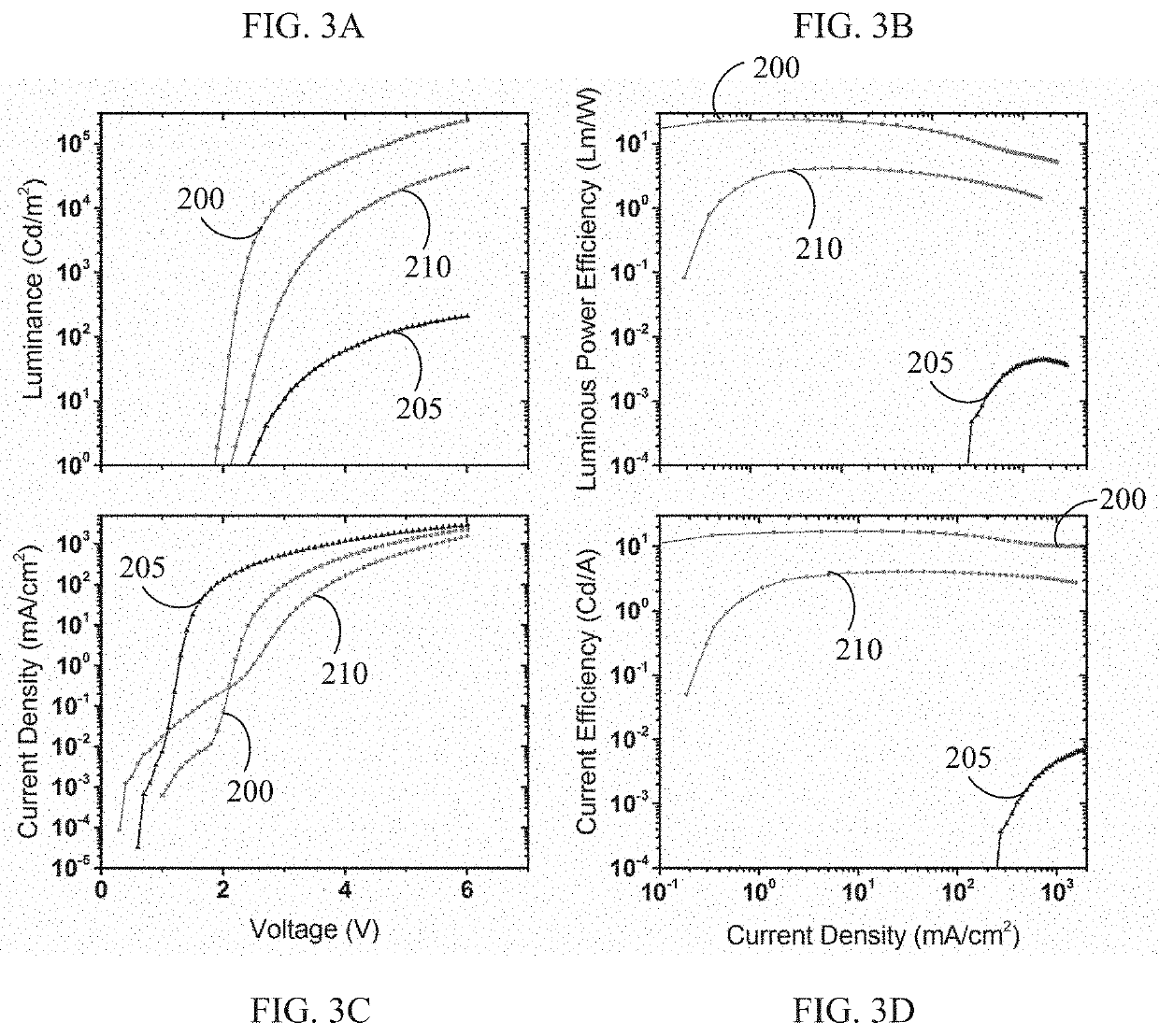
The QLEDs exhibit peak current efficiency and high operational stability, achieving record luminance of over 220,000 cd / m², surpassing previous QLED and OLED devices, with improved tunability and reduced efficiency roll-off at high current densities.

Problems solved by technology

However, despite year of intense research, quantum dot light-emitting diode (QLED) devices that utilize electroluminescence properties of QDs have remained inferior to organic light-emitting diode (OLED) devices in terms of brightness, efficiency, and operational lifetime prior to this invention.
However, they have not received widespread acceptance mainly because of the challenging light source requirements, wherein the ideal light source needs to emit the appropriate color within a narrow emission spectrum to match the absorption peaks of the photosensitizers, needs to exhibit a high enough power density for sufficient excitation but also produce low enough heat to avoid pain for the patients in addition to providing flexible form factors with homogeneous emission so that the light source can be easily applied to the patients without worrying about over or under treatments.
However, these expensive, hot, rigid, heavy and inhomogeneous light sources are not commonly available in small clinics and treatments can only be carried out in limited places and require expensive hospital visits, thereby limiting their further penetration into practical clinical use.
However, existing OLEDs are unable to achieve the required high light brightness (>20,000 cd / m2 or ˜10 mW / cm2) at wavelengths within the deep red region due to the significant efficiency roll-off problems of OLEDs at high current density and the lack of efficient deep red emitters having narrow spectra.

Method used


Image

  • Quantum dot light emitting devices (QLEDs) and method of manufacture
  • Quantum dot light emitting devices (QLEDs) and method of manufacture
  • Quantum dot light emitting devices (QLEDs) and method of manufacture

Examples


Embodiment Construction

[0046]In the following description, for the purposes of explanation, numerous specific details are set forth in order to provide a thorough understanding of the present invention. It will be apparent, however, to one skilled in the art that the present invention may be practiced without these specific details. In order that the invention may be readily understood and put into practical effect, preferred embodiments will now be described by way of the following non-limiting examples.

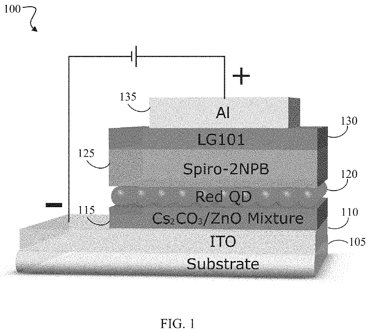
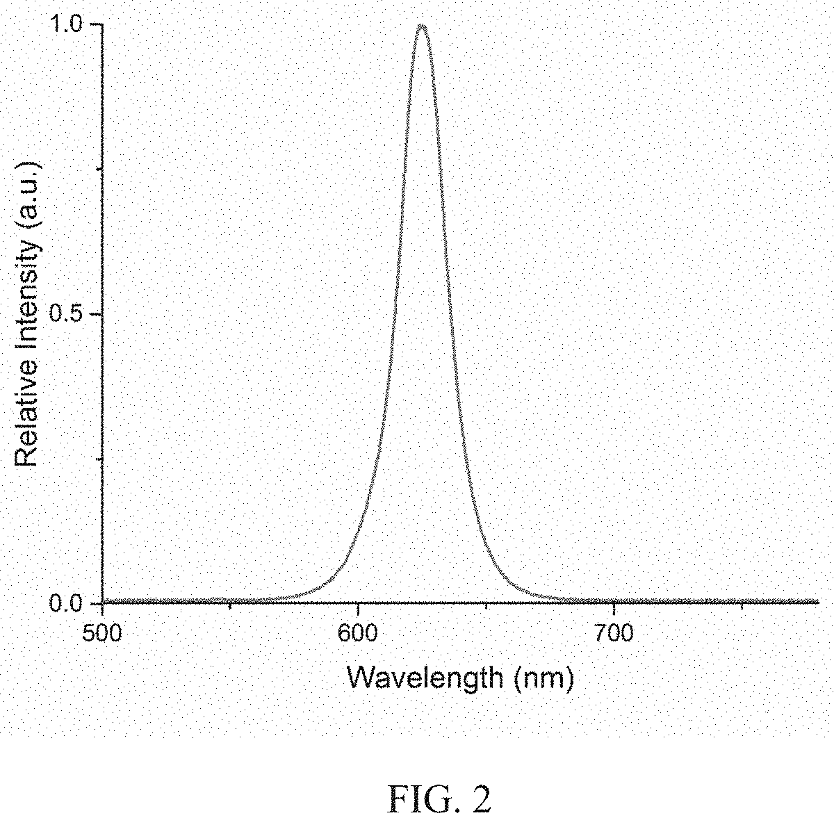
[0047]In various embodiment, methods of making ultrabright quantum dot light-emitting devices (QLEDs) are provided. In general, the methods comprise depositing quantum dot (QD) layers to function as emitters and a mixture layer of metal oxide nanoparticles and alkali metal compounds for the simultaneous electron injection and hole blocking to achieve charging balance at high driving current conditions, and thus ultrahigh brightness which is at least 2 to 3 times higher than maximum brightness of previous ...


PUM

PropertyMeasurementUnit
thicknessaaaaaaaaaa
thicknessaaaaaaaaaa
concentrationaaaaaaaaaa

Abstract

An ultrabright bright quantum dot light-emitting diode (QLED) device and associated method of manufacture. The QLED device includes quantum dots (QD) as emitters and a mixture of metal oxide nanoparticles and alkali metal compounds for simultaneous electron injection and hole blocking to achieve charging balance at high driving current conditions. The ultrabright QLEDs are useful for many light source applications including, but not limited to display, solid state lighting, optical sensor, phototherapy, photomedicine and photobiomedicine.

Description

CROSS-REFERENCE TO RELATED APPLICATIONS[0001]This application claims priority to U.S. Provisional Patent No. 62 / 565,253, entitled, “Ultrabright Quantum Dot Light Emitting Devices (QLEDs) and Method of Manufacture”, filed Sep. 29, 2017, which is incorporated here by reference in its entirety.BACKGROUND OF THE INVENTION[0002]Colloidal quantum dots (QDs) are superior to organic luminescent materials for display and lighting applications due to their narrow emission bandwidths, high photoluminescence quantum efficiency and tenability of their emission spectrum through particle size control. However, despite year of intense research, quantum dot light-emitting diode (QLED) devices that utilize electroluminescence properties of QDs have remained inferior to organic light-emitting diode (OLED) devices in terms of brightness, efficiency, and operational lifetime prior to this invention.[0003]Photomedical applications include photodynamic therapy (PDT) and photobiomodulation (PBM). In PDT, l...

Claims


Application Information

Patent Timeline
Patent Type & Authority Patents(United States)
IPC IPC(8): H01L51/50H01L33/18H01L33/26H01L33/06H01L33/14H01L33/00H01L33/42
CPCH01L51/502H01L33/005H01L33/18H01L33/06H01L33/26H01L33/42H01L51/5048H01L33/14H01L51/5092H01L51/5096H10K50/115H10K50/171H10K50/18H10K50/14
Inventor DONG, YAJIECHEN, HAOWU, SHIN-TSONHE, JUAN
Owner UNIV OF CENT FLORIDA RES FOUND INC
Learn More