
Augmented reality image projection system

a projection system and augmented reality technology, applied in medical science, surgery, diagnostics, etc., can solve the problems of visual discord, conventional augmented reality image projection system, complicated process of aligning projection, etc., to eliminate or minimize the use of additional alignment devices, simple and compact system, and high contrast

Active Publication Date: 2020-03-03
NAT CANCER CENT
View PDF11 Cites 0 Cited by
  • Summary
  • Abstract
  • Description
  • Claims
  • Application Information

AI Technical Summary

Benefits of technology

The Augmented Reality Image Projection System described in this patent is a simple and compact device that aligns the augmented reality image with the real image through a shared optical axis. This avoids the need for additional alignment devices or restrictions, allowing for multiple real-time imaging configurations. Additionally, the system uses an invisible light source that does not interfere with visible light, resulting in high-contrast augmented reality images. The device is also designed in a compact form to minimize operator movement and line of sight blockages, making it easier to use in surgical procedures. Overall, this system provides a versatile and efficient tool for augmented reality imaging in various medical applications.

Problems solved by technology

However, an HMD or a semi-translucent screen is in between the operation site and the operator's eyes so it is prone to be contaminated and may cause a sense of visual discord by interfering with the line of sight partially.
However, a conventional augmented reality image projection system, which is a side-by-side arrangement of two dedicated units of a projection device and a real image capture device, has following issues.
First, it involves a complicated process of aligning the projection onto the subject.
The lack of unity between the projection device for projecting the AR image and the real image capture device which serves as an alignment reference results in their discrepancies in direction and distance.
Such projection system may still have discomfort for the viewer as there may exist a time delay in the projected image.
In addition, as the subject is three-dimensional having a certain thickness, the distance of the subject from the projection system differs portion by portion, which requires an additional calculation time for alignment even if a stereoscopic camera is in use.
Second, a size of the system is hard to be reduced in compact form if each device is configured independently.
As the separately installed camera and projection device may occupy a large space, 1) it may block the line of sight of the observer who needs to see an AR image projected onto the subject, which limits the usability of the system.
Size reduction of the AR image projection system is not feasible in typical projection system having separate devices for projecting and imaging including positional information.
Third, it is technically difficult to implement additional real-time imaging device such as a fluorescence imaging device.
Additional imaging device requires additional trackers or complicated calculation for image alignment.
Physical realization is hard as additional devices are necessary according to the additional number of images.
It becomes very complicated system occupying a lot of space.
Fourth, interference between the projection image and the illumination of the subject diminishes the contrast of projected AR image.
Additional fluorescence image further makes it difficult to configure the system as it interferes with the excitation light source.
In this case, increasing the intensity of the illumination to improve the captured image quality 1) makes the projected image less visible and 2) results in an adverse effect on alignment as the projection image is taken together with the real image.
Such device includes a complicated method using time-division illumination and toggling between illumination and image projection to prevent such interference.
However, this approach makes the system complex and also brings serious inconvenience to the user's view due to the flashing illumination.
3) In case a fluorescent image is appended, an additional time division is required as the white light illumination interferes with the excitation illumination which prevents simultaneous acquisition and projection of the images.
Previous AR projection system is unable to solve the interference issue between illumination, projection image, and special imaging.
Such interference is a problem needed to be solved to build a practical working system.

Method used


Image

  • Augmented reality image projection system
  • Augmented reality image projection system
  • Augmented reality image projection system

Examples


first embodiment

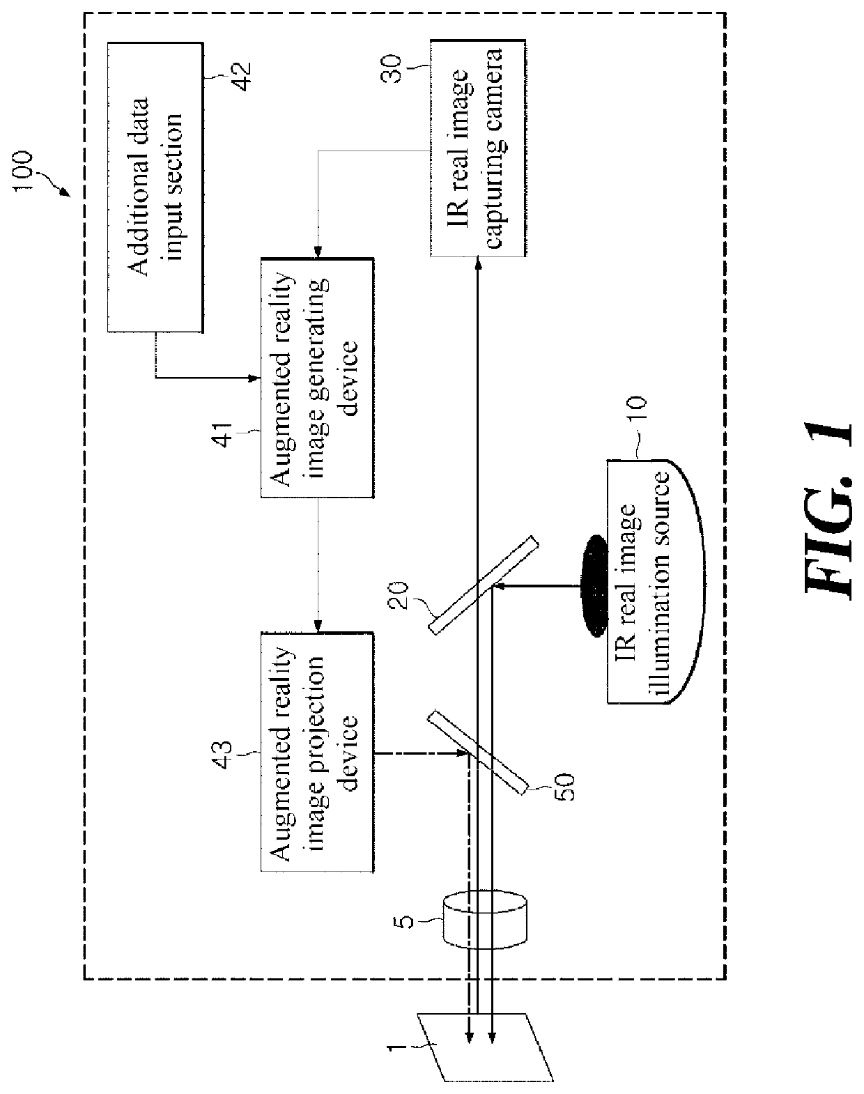
[0044]FIG. 1 is a schematic diagram of the augmented reality image projection system according to the present disclosure. The AR image projection system includes an IR (infrared) real image illumination source 10, a beam splitter 20, an IR real-image-capturing camera or simply IR real image camera 30, an AR (augmented reality) image generating device 41, an additional data input section 42, an AR image projection device 43, and a dichroic mirror 50.

[0045]The IR real image illumination source 10 provides illumination light for capturing a real image for the IR real image camera 30. In some embodiments, the IR real image illumination source 10 provides infrared illumination light having no interference with visible rays for enabling the AR image projection device 43 to project a contrasty AR image.

[0046]The beam splitter 20, which is a light deflection means, distributes an infrared ray by 50:50 ratio. The beam splitter 20 reflects the light rays from the IR real image illumination so...

second embodiment

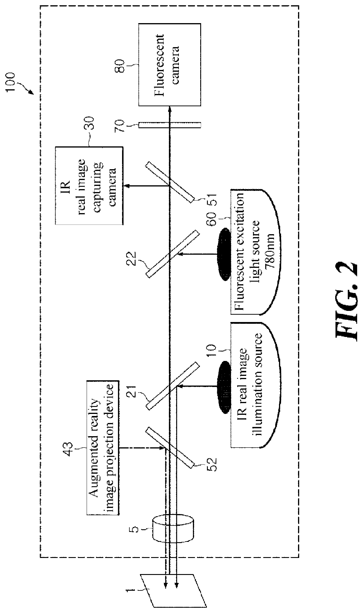
[0052]FIG. 2 is a schematic diagram of the AR image projection system among some embodiments of the present disclosure, including an IR real image illumination source 10, a first beam splitter 21, an IR real image camera 30, a first dichroic mirror 51, a fluorescent excitation light source 60, a second beam splitter 22, a fluorescent camera 80, a filter 70, an AR image projection device 43, and a second dichroic mirror 52.

[0053]This second embodiment according to the present disclosure shows an example case of adding a fluorescent image to a virtual image generated by the computer along with the same optical axis of the system. The specific forms and locations of the beam splitters and the dichroic mirrors may vary according to the wavelength of the fluorescence.

[0054]In the second embodiment according to the present disclosure, the fluorescent excitation light source 60 provides excitation light of 780 nm, then the second beam splitter 22 reflects the excitation light and transmits...


PUM


Abstract

The present disclosure relates to an augmented reality (AR) image projection system capable of simultaneously capturing a real image and projecting an AR image, and capable of applying same to a subject requiring precise work or in an environment having spatial restrictions. The present disclosure includes a real image capture device for capturing a real image illuminated by invisible rays without interference with visible rays, and an AR image projection device for projecting an AR image, wherein the real image capture device captures a real image and the AR image projection device projects an AR image through the same optical axis. Further, the present disclosure includes a real image capture device, an AR image projection device, as well as additional imaging devices such as a fluorescent camera configured integrally along the same optical axis, and configured to avoid wavelength interference between a light source and an excitation light and the like.

Description

CROSS-REFERENCE TO RELATED APPLICATION[0001]The present application is the US national phase of International Patent Application No. PCT / KR2016 / 001049, filed Feb. 1, 2016, which claims priority to Korean Patent Application No. 10-2015-0032371, filed on Mar. 9, 2015. The disclosures of the above-listed applications are hereby incorporated by reference herein in their entirety.TECHNICAL FIELD[0002]The present disclosure in some embodiments relates to a technology for projecting an augmented reality (AR) image. More particularly, the present disclosure relates to an augmented reality projection system which is capable of simultaneously capturing the real image and projecting the augmented reality image, and is applicable to geometrically restricted spaces and / or to an object subject to a precision operation.BACKGROUND[0003]In general, augmented reality is a technology for showing computer generated graphics (virtual images) overlapped with a real image to make the viewer feel as if the...

Claims


Application Information

Patent Timeline
Patent Type & Authority Patents(United States)
IPC IPC(8): A61B90/00A61B1/313A61B1/04
CPCA61B90/361A61B90/37A61B1/043A61B90/36A61B1/313A61B2090/365A61B2090/366A61B1/0605
Inventor KIM, SEOK KIKIM, SEONG CHEONPARK, SUN UP
Owner NAT CANCER CENT
Learn More