Separator and aluminum electrolytic capacitor

a technology of aluminum electrolytic capacitor and separator, which is applied in the direction of cell components, cell component details, electrochemical generators, etc., can solve the problems of self-heating of the capacitor due to power loss, reducing the basis weight of the separator, and increasing the requirement for impedance reduction, so as to improve the short circuit defect rate, excellent tearing strength, and denseness and impedance performance.

Active Publication Date: 2020-02-18
NIPPON KODOSHI
View PDF33 Cites 0 Cited by
  • Summary
  • Abstract
  • Description
  • Claims
  • Application Information

AI Technical Summary

Benefits of technology

[0068]According to the present invention, it is possible to provide the separator for the aluminum electrolytic capacitor, which is excellent in the tearing strength, denseness and impedance performance.
[0069]Moreover, it is possible to provide the aluminum electrolytic capacitor having an excellent impedance performance, and capable of improving short circuit defect rate and enhancing yield, by the use of the separator.

Problems solved by technology

When a ripple current is applied to the aluminum electrolytic capacitor, the capacitor is self-heated due to loss of power.
The heat generation in the aluminum electrolytic capacitor is a factor that directly affects the lifetime, and since the reduction in the heat generation results in prolongation of the lifetime, the requirement for the impedance reduction becomes higher.
However, there are caused various problems in mere reduction of the basis weight of the separator, reduction of the density, and making the thickness thin.
Accordingly, in case of the use in the aluminum electrolytic capacitor, there is a problem that an element short circuit defect rate and an aging short circuit defect rate are increased, and even if short-circuiting does not occur, the short circuit defect rates of products after coming onto the market are increased.
As a result, during the manufacturing step of the aluminum electrolytic capacitor, the separator is broken to lower productivity and yield.
However, when the thickness of the separator is made large and the density is increased, the impedance is worsened.
At that time, when the tearing strength of the separator is weak, there is a case where the separator is broken to lower the yield.

Method used


Image

  • Separator and aluminum electrolytic capacitor

Examples


example 1

Conventional Example 1

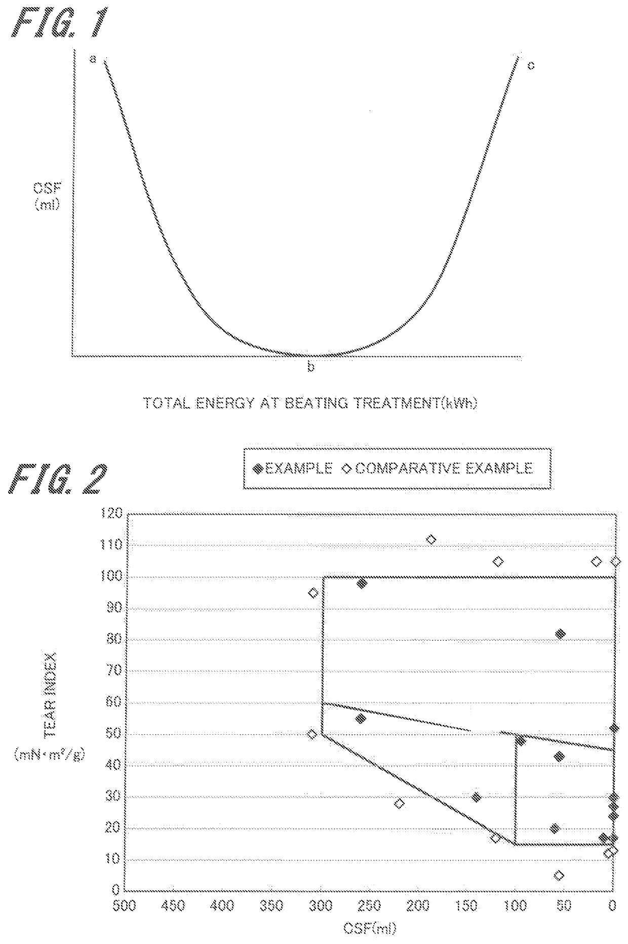
[0153]By the use of a papermaking raw material having a CSF value of 160 ml in which the CSF value is once lowered to 0 ml (lower limit) and then turns upward by further beating a Lyocell fiber being a regenerated cellulose fiber, there was obtained a sheet by a Fourdrinier papermaking method. Subsequently, according to the method of Example 1 of JP 2006-253728 A, the sheet was subjected to paper-strengthening processing to give a separator having a thickness of 20.0 μm, a density of 0.425 g / cm3, and a tear index of 6 mN·m2 / g. A CSF value of the thus obtained separator was 150 ml.

[0154]There was formed, by the use of the separator, an aluminum electrolytic capacitor element having a rated voltage of 6.3 V, a capacity of 1000 μF, and an element outer diameter of 7.9 mm, and after impregnation with a GBL-based electrolytic solution, an aluminum electrolytic capacitor of Conventional Example 1 was produced by inserting the element in a casing and sealing the eleme...

example 2

Conventional Example 2

[0155]There was obtained, according to the method of Example 1 of JP 53-142652 A and by a cylinder paper method, a separator having a thickness of 40.0 μm, a density of 0.400 g / cm3, and a tear index of 43 mN·m2 / g. A CSF value of the thus obtained separator was 620 ml.

[0156]There was formed, by the use of the separator, an aluminum electrolytic capacitor element having a rated voltage of 6.3 V, a capacity of 1000 μF, and an element outer diameter of 8.5 mm, and after impregnation with a GBL-based electrolytic solution, an aluminum electrolytic capacitor of Conventional Example 2 was produced by inserting the element, in a casing and sealing the element.

Example 4

[0157]There was used a papermaking raw material obtained by blending, as the fiber A, 20% by mass of a polynosic rayon fiber being a regenerated cellulose, fiber having a CSF value of 0 ml, and as the fiber B, 80% by mass of a polynosic rayon fiber being a regenerated cellulose fiber having a CSF value of...

example 3

Conventional Example 3

[0167]There was obtained, by the use of a regenerated cellulose fiber having a CSF value of 0 ml as a papermaking raw material, a separator having a thickness of 30.0 μm, a density of 0.400 g / cm3, and a tear index of 7 mN·m2 / g by a Fourdrinier papermaking method. A CSF value of the thus obtained separator was 0 ml.

[0168]There was formed, by the use of the separator, an aluminum electrolytic capacitor element having a rated voltage of 16 V, a capacity of 550 μF, and an element outer diameter of 9.2 mm, and after impregnation with a GBL-based electrolytic solution, an aluminum electrolytic capacitor of Conventional Example 3 was produced by inserting the element in a casing and sealing the element.


PUM

PropertyMeasurementUnit
thicknessaaaaaaaaaa
densityaaaaaaaaaa
diameteraaaaaaaaaa

Abstract

Provided is a separator having excellent tearing strength, denseness, and impedance performance, and an aluminum electrolytic capacitor provided with the separator. The present invention constitutes a separator including beatable regenerated cellulose fibers, the separator having a CSF value X[ml] and tear index Y[mN·m2 / g] within the ranges satisfying the following formulae. The present invention also constitutes an aluminum electrolytic capacitor in which at least one of the separators is used, the capacitor feeing formed by interposing the separator between an anode and a cathode.0≤X≤300  Formula 1 15≤Y≤100  Formula 2 Y≥0.175X−2.5  Formula 3

Description

TECHNICAL FIELD[0001]The present invention relates to a separator that is suitable for an aluminum electrolytic capacitor, and an aluminum electrolytic capacitor using the separator.BACKGROUND ART[0002]Recently, along with electronization of automobile-related equipment and digital equipment, energy saving has advanced, and there is a demand for impedance reduction and lifetime elongation of parts to be mounted thereon. In addition, due to the impedance reduction of parts to be mounted thereon, there are attained many merits such as reduction in power loss, response to voltage reduction of semiconductor operating power and increase in operating speed, and enhancement of frequency characteristics.[0003]Furthermore, due to an energy serving policy and an alternative energy policy to oil by not only Japan but also by every country in the world, the utilization of inverter circuits or the like each having good energy efficiency has been continuously expanded in every field related to en...

Claims


Application Information

Patent Timeline
Patent Type & Authority Patents(United States)
IPC IPC(8): H01G9/02H01G11/52H01M2/16H01G9/045H01M10/05H01M10/052H01M10/0525H01M50/429H01M50/489
CPCH01G9/045H01G11/52H01M2/162H01G9/02H01M10/05Y02E60/13H01M10/0525H01M10/052H01M2/1626Y02E60/10H01M50/44H01M50/429H01M50/489H01M50/4295
Inventor IGAWA, ATSUSHIFUJIMOTO, NAOKITAKEUCHI, AKIYOSHIWADA, NORIHIRO
Owner NIPPON KODOSHI
Why Eureka
Try Eureka