Vehicular automatic transmission

a technology of automatic transmission and spline engagement, which is applied in the direction of gearing details, transportation and packaging, gearing, etc., can solve the problems of increasing the mass reducing the transmission efficiency of the automatic transmission, and increasing the manufacturing cost, so as to reduce the effect of cancelling torque fluctuation by use of collisions, reducing the effect of spline engagement portion backlash, and reducing the displacement of the spline engagement portion

Active Publication Date: 2020-02-18
TOYOTA JIDOSHA KK
View PDF25 Cites 0 Cited by
  • Summary
  • Abstract
  • Description
  • Claims
  • Application Information

AI Technical Summary

Benefits of technology

[0006]As described in JP 2006-283955 A, torque fluctuation delivered from the output shaft of the automatic transmission is suppressed or reduced by making it possible to change the inertia in the vehicular automatic transmission. However, separately providing the inertia member may result in increase of the mass of the automatic transmission, and the transmission efficiency of the automatic transmission may be reduced. Also, a device or arrangement for engaging the inertia member with the rotating body is needed, resulting in increase of the manufacturing cost.
[0007]This present disclosure provides a vehicular automatic transmission including a plurality of planetary gear sets and a plurality of engagement devices, wherein torque fluctuation delivered from the vehicular automatic transmission can be suppressed, without significantly increasing the number of components.
[0009]With the vehicular automatic transmission configured according to the above aspect of the present disclosure, when a predetermined gear position is established, the above-indicated at least one rotating element, to which no torque is transmitted, is co-rotated by another rotating element. At this time, the at least one rotating element, which is coupled via the spline engagement portion, rotates while colliding with spline teeth defining backlash formed in the rotating direction in the spline engagement portion. In a region in which the engine speed is low, the varying displacement of the spline engagement portion due to torque fluctuation of the engine is large; therefore, collisions are repeated in the spline engagement portion. Owing to the collisions, the energy of inertia due to torque fluctuation of the engine is consumed, and torque fluctuation delivered from the output shaft of the automatic transmission can be suppressed. Also, in order to suppress torque fluctuation, there is no need to add a new component, such as an inertia member, for suppressing the torque fluctuation.
[0011]With the vehicular automatic transmission configured as described above, as the rotational speed of the engine increases, the varying displacement of the spline engagement portion is reduced, and collisions are less likely to occur in the spline engagement portion; therefore, the effect of cancelling torque fluctuation by use of the collisions is reduced. On the other hand, when the tolerance ring is provided between the above-indicated at least one rotating element, and a part of the rotating element of the other planetary gear set or the engagement device, backlash in the spline engagement portion is substantially eliminated. Accordingly, backlash formed on the power transmission path consists solely of backlash formed at meshing parts of gears, or the like, other than the spline engagement portion; therefore, the backlash is sufficiently reduced. As a result, the frequency of collisions between tooth faces defining backlash increases even after the engine speed increases, and the torque fluctuation can be suppressed, through consumption of the energy of inertia due to the collisions.

Problems solved by technology

However, separately providing the inertia member may result in increase of the mass of the automatic transmission, and the transmission efficiency of the automatic transmission may be reduced.
Also, a device or arrangement for engaging the inertia member with the rotating body is needed, resulting in increase of the manufacturing cost.
In a region in which the engine speed is low, the varying displacement of the spline engagement portion due to torque fluctuation of the engine is large; therefore, collisions are repeated in the spline engagement portion.

Method used


Image

  • Vehicular automatic transmission
  • Vehicular automatic transmission
  • Vehicular automatic transmission

Examples


Embodiment Construction

[0024]One embodiment of the present disclosure will be described in detail with reference to the drawings. In the following embodiment, some components or parts in the drawings are simplified or deformed as needed, and the dimension ratios, shapes, etc. of the respective components or parts are not necessarily accurate.

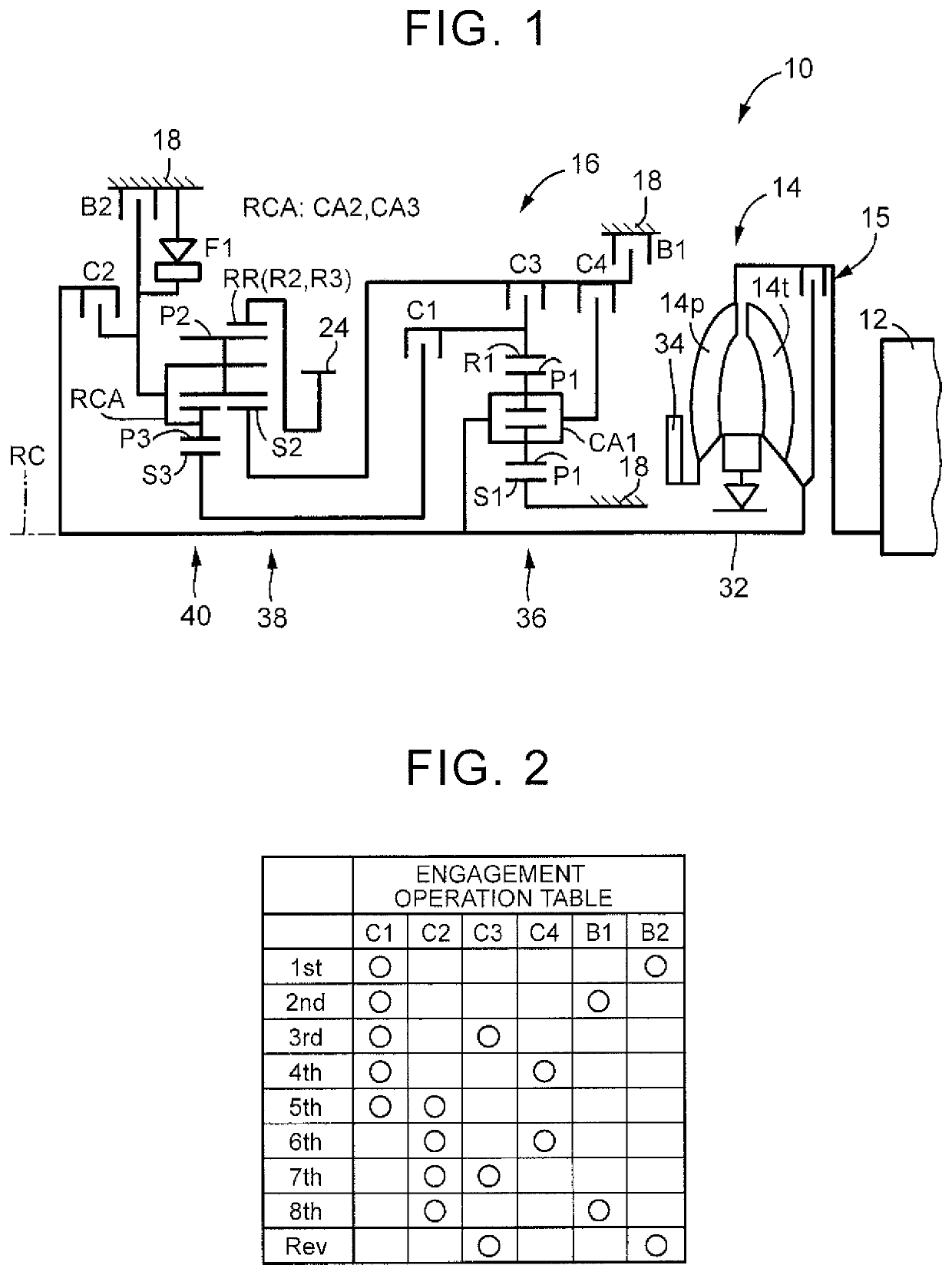
[0025]FIG. 1 is a skeleton diagram of a vehicular drive train 10 to which this present disclosure is applied. The vehicular drive train 10 includes an engine 12, a torque converter 14, and an automatic transmission 16. The torque converter 14 and the automatic transmission 16 are constructed generally symmetrically with respect to a center line (axis RC), and the lower half of each device below the center line is not depicted in FIG. 1. The axis RC in FIG. 1 is the axis of rotation of the engine 12, torque converter 14, and the automatic transmission 16.

[0026]In FIG. 1, the torque converter 14 is arranged to rotate about the axis RC, and includes a pump impeller 14p c...


PUM


Abstract

A vehicular automatic transmission includes a plurality of engagement devices and a plurality of planetary gear sets. Each of the planetary gear sets includes rotating elements. At least one of the rotating elements of one of the plurality of planetary gear sets is coupled to one of the rotating elements of another planetary gear set or one of the engagement devices, via a spline engagement portion. The rotating elements other than the at least one of the rotating elements coupled via the spline engagement portion is coupled to another rotating element or a non-rotary member directly or via one of the engagement devices. The at least one of the rotating elements coupled via the spline engagement portion is configured to be co-rotated with no torque transmitted via the spline engagement portion, when the automatic transmission is placed in a predetermined gear position as one of the plurality of gear positions.

Description

INCORPORATION BY REFERENCE[0001]The disclosure of Japanese Patent Application No. 2015-231101 filed on Nov. 26, 2015 including the specification, drawings and abstract is incorporated herein by reference in its entirety.BACKGROUND[0002]1. Technical Field[0003]The present disclosure relates to a vehicular automatic transmission, and is particularly concerned with a technology for suppressing torque fluctuation delivered from an output shaft of the vehicular automatic transmission.[0004]2. Description of Related Art[0005]A vehicular automatic transmission is known which consists of a plurality of planetary gear sets and a plurality of engagement devices, and is shifted to one of a plurality of gear positions when a selected one(s) of the engagement devices is switched between an engaged state and a released state. In the vehicular automatic transmission, some technologies for preventing torque fluctuation of an engine from being delivered to an output shaft of the automatic transmissi...

Claims


Application Information

Patent Timeline
Patent Type & Authority Patents(United States)
IPC IPC(8): F16H57/00F16H3/66
CPCF16H3/666F16H3/663F16H57/0006F16H2200/2082F16H2200/2046F16H2200/2066F16H2200/201F16H2200/006F16H3/66F16H57/12F16H2200/202F16H2057/0012F16H3/62F16H37/04F16H57/00
Inventor IKEMURA, MASASHIOTA, HIROFUMIHAGINO, YASUYUKITOYODA, MITSUHIROMICHIKOSHI, YOSUKE
Owner TOYOTA JIDOSHA KK
Why Eureka
Try Eureka