Ink drying device and printing system

a drying device and printing system technology, applied in printing, other printing apparatus, etc., can solve the problem of difficult transmission of heat from the heater to the surface of the recording medium, and achieve the effect of preventing the drying of ink from becoming difficult and efficiently drying the ink

Active Publication Date: 2020-02-18
ROLAND DG CORP
View PDF4 Cites 0 Cited by
  • Summary
  • Abstract
  • Description
  • Claims
  • Application Information

AI Technical Summary

Benefits of technology

[0008]With the ink drying device, heat generated by the heat generator is discharged, together with air, via the discharge holes in the counter plate to the outside of the main body. The heat discharged to the outside of the main body is diffused by the heat diffusion layer and reaches the ink injected onto the recording medium. As a result, the ink injected onto the recording medium is directly dried by the heat diffused by the heat diffusion layer. Therefore, even if the recording medium is relatively thick, the ink is dried efficiently by the heat diffused by the ink diffusion layer. This prevents the drying of the ink from becoming difficult due to, for example, the thickness of the recording medium.

Problems solved by technology

In the case where the recording device disclosed in Japanese Laid-Open Patent Publication No. 2013-184383 performs printing on a relatively thick recording medium, it may be difficult for the heat of the platen heated by the heater to be transmitted to a surface of the recording medium.

Method used


Image

  • Ink drying device and printing system
  • Ink drying device and printing system
  • Ink drying device and printing system

Examples


embodiment 1

Preferred Embodiment 1

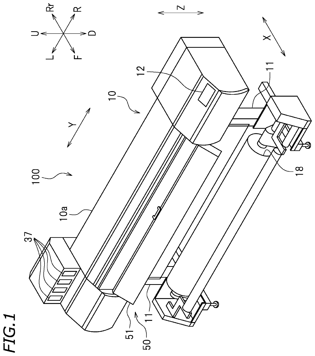
[0026]FIG. 1 is a perspective view of a printing system 100 according to this preferred embodiment. In the following description, directions are defined as follows with respect to a user in front of the printing system 100: a direction approaching the user from the printing system 100 is defined as “forward”, and a direction spaced from the user toward the printing system 100 is defined as “rearward”. The terms “left”, “right”, “up” and “down” refer to left, right, up and down with respect to the printing system 100 as seen in a front view thereof. In the drawings, letters F, Rr, L, R, U and D respectively represent “front”, “rear”, “left”, “right”, “up” and “down”. In the drawings, letter “Y” represents a main scanning direction. Herein, the main scanning direction Y is a left-right direction. Letter “X” represents a sub scanning direction. Herein, the sub scanning direction is a front-rear direction. The sub scanning direction X is perpendicular to the main s...

embodiment 2

Preferred Embodiment 2

[0080]Now, an ink drying device 150 according to preferred embodiment 2 will be described. FIG. 13 is a front view of the ink drying device 150 according to preferred embodiment 2. FIG. 14 is a right side view of a printing system 200 according to preferred embodiment 2. In preferred embodiment 1, the ink drying device 50 preferably is attached to the printing device 10 as shown in FIG. 1. An ink drying device according to the present invention does not need to be attached to the printing device 10. In preferred embodiment 2, for example, as shown in FIG. 13, the ink drying device 150 preferably is independent from the printing device 10. The ink drying device 150 includes the main body 51 that is the same or substantially the same as that in preferred embodiment 1.

[0081]In this example, the ink drying device 150 includes legs 151. The legs 151 are attached to the main body 51. In this preferred embodiment, two legs 151 are respectively attached to a left end a...


PUM


Abstract

An ink drying device dries ink injected onto a recording medium. The ink drying device includes a main body including a counter plate facing the recording medium and including an inner space, and a heat generator located in the inner space of the main body to generate heat. The counter plate is provided with a plurality of discharge holes. The ink drying device further includes a heat diffusion layer provided on an outer surface of the counter plate that faces the recording medium.

Description

CROSS REFERENCE TO RELATED APPLICATIONS[0001]This application claims the benefit of priority to Japanese Patent Application No. 2017-055539 filed on Mar. 22, 2017. The entire contents of this application are hereby incorporated herein by reference.BACKGROUND OF THE INVENTION1. Field of the Invention[0002]The present invention relates to an ink drying device and a printing system.2. Description of the Related Art[0003]Conventionally, a printing device represented by, for example, an inkjet printer is known. This type of printing device includes, for example, a platen on which a recording medium is to be placed, and an ink head that injects ink toward the recording medium placed on the platen.[0004]For example, Japanese Laid-Open Patent Publication No. 2013-184383 discloses an inkjet recording device including a heater that heats a platen. In the recording device disclosed in Japanese Laid-Open Patent Publication No. 2013-184383, the platen is heated by the heater, and thus the record...

Claims


Application Information

Patent Timeline
Patent Type & Authority Patents(United States)
IPC IPC(8): B41J11/00B41J11/06B41J11/057B41J2/32
CPCB41J11/002B41J11/06B41J2/32B41J11/057B41J11/0024B41J11/0022
Inventor MATSUOKA, HISAYA
Owner ROLAND DG CORP
Why Eureka
Try Eureka