Image forming apparatus

a technology of forming apparatus and forming tube, which is applied in the direction of electrographic process apparatus, printing, instruments, etc., can solve the problems of insufficient prevention of image displacement, difficult to prevent image displacement, and in the sub-scanning direction of image displacemen

Inactive Publication Date: 2011-08-30
RICOH KK
View PDF37 Cites 1 Cited by
  • Summary
  • Abstract
  • Description
  • Claims
  • Application Information

AI Technical Summary

Benefits of technology

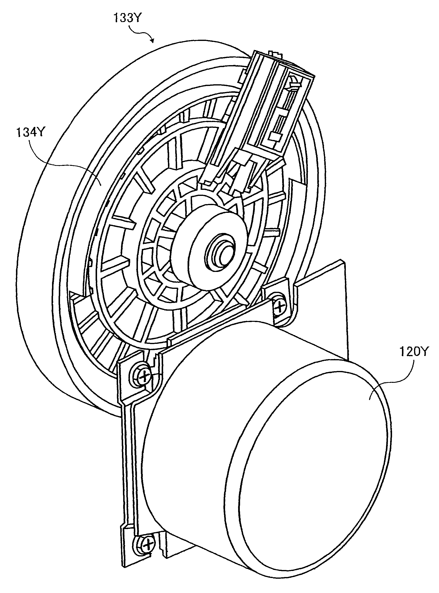
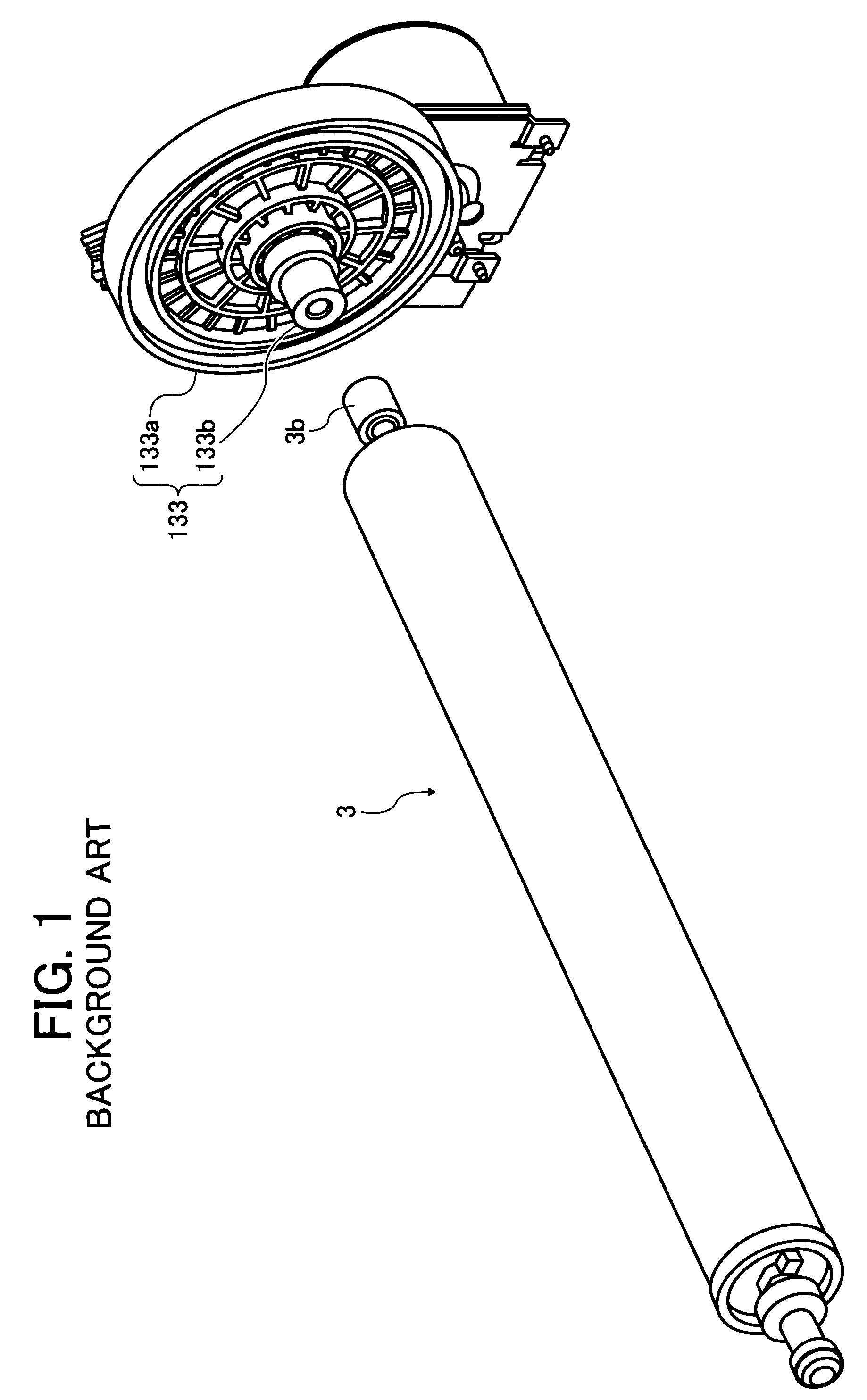
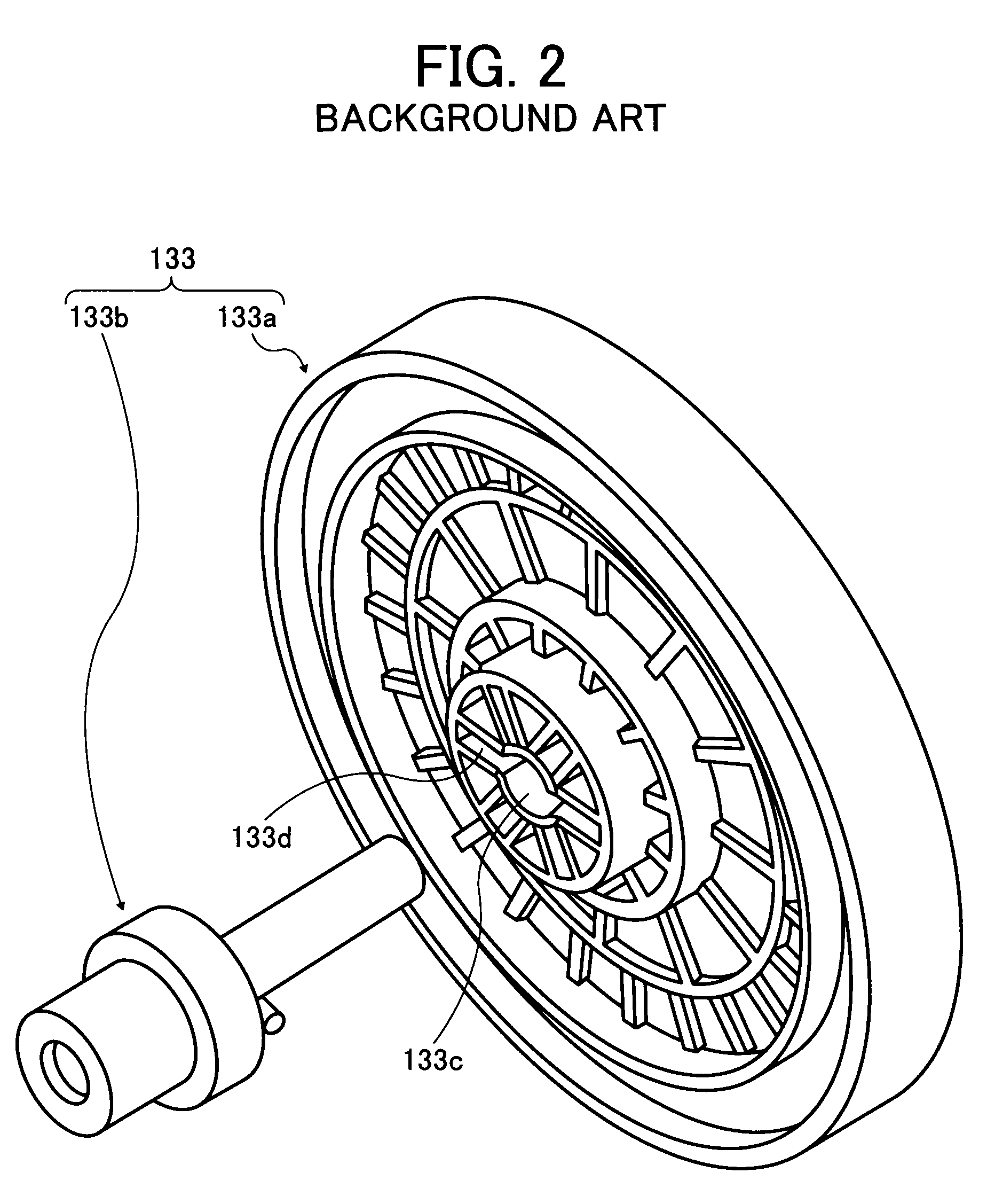
[0016]In the image forming apparatus having the above-described configuration, a slight rattling movement may be produced between the gear portion 133a and the engaging portion 133b inserted thereto due to an error in the dimensional accuracy of the gear portion 133a or the engaging portion 133b. Due to this rattling, the velocity fluctuation pattern of the photosensitive element gear 133 per rotation slightly varies from rotation to rotation. As a result, the drive velocity pattern detected based on the predetermined detection toner images as described above does not match the actual velocity fluctuation pattern during image formation, which makes prevention of image displacement difficult.

Problems solved by technology

This causes dot displacement, resulting in image displacement in the sub-scanning direction.
However, there are some cases in which driving each photosensitive element according to the drive velocity pattern or adjusting the phase of the velocity fluctuation pattern of each photosensitive element is not sufficient to prevent image displacement.
As a result, the drive velocity pattern detected based on the predetermined detection toner images as described above does not match the actual velocity fluctuation pattern during image formation, which makes prevention of image displacement difficult.

Method used


Image

  • Image forming apparatus
  • Image forming apparatus
  • Image forming apparatus

Examples


Embodiment Construction

[0042]In describing preferred embodiments illustrated in the drawings, specific terminology is employed for the sake of clarity. However, the disclosure of this patent specification is not intended to be limited to the specific terminology so selected and it is to be understood that each specific element includes all technical equivalents that operate in a similar manner.

[0043]Referring now to the drawings, wherein like reference numerals designate identical or corresponding parts throughout the several views thereof, particularly to FIG. 23, image forming apparatuses according to exemplary embodiments of the present invention are described.

[0044]FIG. 3 is a diagram illustrating a schematic configuration of an electrophotographic printer (hereinafter referred to as printer) according to an embodiment of the present invention. The printer includes four process units 1Y, 1C, 1M, and 1K that form toner images of yellow, cyan, magenta, and black, which are abbreviated as Y, C, M, and K,...


PUM


Abstract

An image forming apparatus that includes a plurality of image bearing members, a plurality of drive sources each including a drive gear, a plurality of driven gears, a visible image forming unit, an endless traveling member, a transfer unit, an image detection unit, and a controller. The controller controls rotation of the plurality of image bearing members according to a velocity fluctuation pattern of each surface of the image bearing members based on a detection time interval between predetermined visible detection images formed on the surface of the image bearing member and transferred therefrom to the endless traveling member detected by the image detection unit. Each of the plurality of driven gears includes a gear portion and an engaging portion integrated therewith. The gear portion includes a geared circumference and the engaging portion engages the image bearing member.

Description

CROSS-REFERENCE TO RELATED APPLICATION[0001]This patent specification is based on and claims priority from Japanese Patent Application No. 2007-004090 filed on Jan. 12, 2007 in the Japan Patent Office, the entire contents of which are hereby incorporated by reference herein.BACKGROUND[0002]1. Field of the Invention[0003]The present invention relates to an image forming apparatus.[0004]2. Description of the Related Art[0005]In an image forming apparatus such as a copier, a facsimile machine, or a printer, visible images are formed, for example, on each of a plurality of rotating image bearing members such as photosensitive elements and transferred at transfer positions to an endless traveling member such as an intermediate transfer belt or a recording medium held on the endless traveling member, such that the visible images are superimposed one atop another. In this type of the image forming apparatus, each of the visible images may be displaced from each other in a sub-scanning dire...

Claims


Application Information

Patent Timeline
Patent Type & Authority Patents(United States)
IPC IPC(8): G03G15/00
CPCG03G15/0131G03G15/5008G03G15/0194G03G2215/00075G03G2215/0138G03G2215/0158G03G2215/0122
Inventor FUNAMOTO, NORIAKIEBARA, JOHKOBAYASHI, KAZUHIKOSUGIYAMA, KEISUKEUCHIDA, TOSHIYUKIEHARA, YASUHISA
Owner RICOH KK
Why Eureka
Try Eureka