Digital amplitude modulation device and digital amplitude modulation control method

a digital amplitude modulation and control method technology, applied in the direction of rf amplifiers, amplifiers with semiconductor devices/discharge tubes, gated amplifiers, etc., can solve the problem of deteriorating signal quality of am waves, and achieve the effect of preventing damage to power amplifiers

Inactive Publication Date: 2016-11-10
KK TOSHIBA
View PDF4 Cites 0 Cited by
  • Summary
  • Abstract
  • Description
  • Claims
  • Application Information

AI Technical Summary

Benefits of technology

[0010]This makes it difficult to prevent the power amplifiers in the digital amplitude modulation device from being damaged. Moreover, the same problem arises in a digital circuit including a complex programmable logic device (CPLD) or a field programmable gate array (FPGA) for the control to prevent a damage of power amplifiers.

Problems solved by technology

In this type of digital amplitude modulation device, the signal quality of AM waves may be deteriorated when some kind of failure, such as breakage of a power amplifier, or short circuit or disconnection of a joint portion, occurs.

Method used


Image

  • Digital amplitude modulation device and digital amplitude modulation control method
  • Digital amplitude modulation device and digital amplitude modulation control method
  • Digital amplitude modulation device and digital amplitude modulation control method

Examples


first embodiment

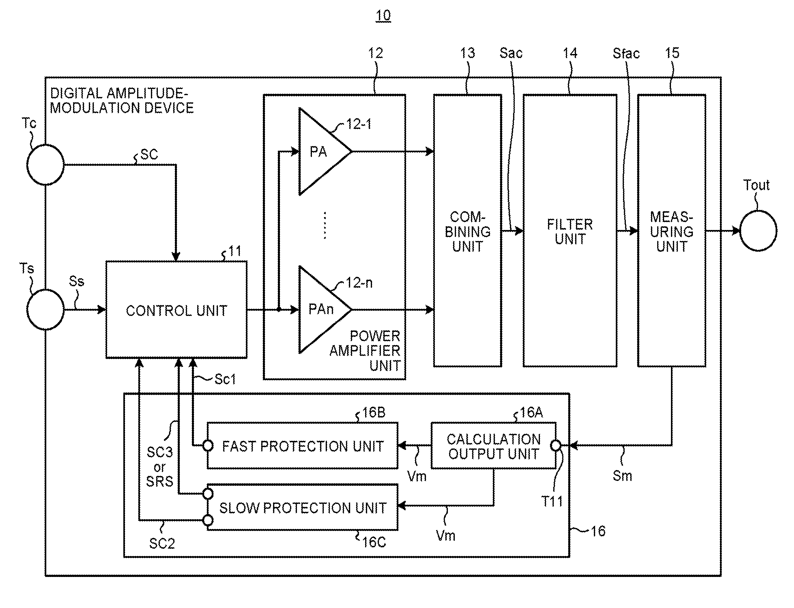
[0029]FIG. 1 is a functional configuration block diagram of a digital amplitude modulation device of a first embodiment.

[0030]A digital amplitude-modulation device 10 generally includes a control unit 11, a power amplifier unit 12, a combining unit 13, a filter unit 14, a measuring unit 15, a protection unit 16, a carrier-signal input terminal Tc, and a sound-signal input terminal Ts.

[0031]To the carrier-signal input terminal Tc, a carrier signal Sc as a transmission signal is input.

[0032]To the sound-signal input terminal Ts, a sound signal Ss, which is a modulation signal, is input.

[0033]The control unit 11 controls the overall digital amplitude-modulation device 10 as described later.

[0034]The power amplifier unit 12 includes n power amplifiers (PA) 12-1 to 12-n. The carrier signal input to the carrier-signal input terminal 101 is input to the power amplifiers 12-1 to 12-n through the control unit 11.

[0035]The ON / OFF of the respective power amplifiers 12-1 to 12-n are controlled ...

second embodiment

[2] Second Embodiment

[0171]Next, a second embodiment will be explained.

[0172]FIG. 9 is a functional configuration block diagram of a digital amplitude modulation device according to the second embodiment.

[0173]In FIG. 9, same or like reference symbols are assigned to same or like elements as those in FIG. 1.

[0174]A digital amplitude-modulation device 10A includes, as shown in FIG. 9, the control unit 11, the power amplifier unit 12, the combining unit 13, a measuring unit 17, the filter unit 14, the protection unit 16, the carrier-signal input terminal Tc, and the sound-signal input terminal Ts, and the signal output terminal Tout.

[0175]The digital amplitude-modulation device 10A according to the second embodiment differs in that in place of the measuring unit 15 of the digital amplitude-modulation device 10 of the first embodiment, the measuring unit 15A is positioned in the stage following the combining unit 13 and preceding the filter unit 14.

[0176]The measuring unit 15A measures...


PUM


Abstract

A calculation output unit of a digital amplitude modulation device calculates and outputs a protection index of an amplifier based on a combined output signal or an amplitude modulation signal. A first protection unit outputs to a control unit a first control signal to place an entire amplifier unit in an off-controlled state, based on the protection index. A second protection unit outputs, to the control unit, a second control signal to control an upper limit number of amplifier units that can be on-controlled in parallel and a third control signal to on / off control the upper limit number or less or the initial number of the amplifiers. The control unit on / off controls the power amplifiers based on an input sound signal, the first control signal, the second control signal, and the third control signal.

Description

FIELD[0001]The present invention relates to a digital amplitude modulation device and a digital amplitude modulation control method.BACKGROUND[0002]Conventionally, a medium-wave broadcast transmitter uses a digital amplitude modulation device.[0003]The digital amplitude modulation device includes multiple power amplifiers that are connected in parallel.[0004]By controlling ON / OFF of the power amplifiers according to a voltage amplitude level of a modulation signal such as a sound signal provided externally, a carrier signal is amplified while the number of power amplifiers to be concurrently placed in ON state is changed.[0005]Output signals from the power amplifiers in on the concurrent ON state are then combined to generate an amplitude modulation (AM) wave, and the generated AM wave is transmitted to a predetermined broadcast service area.[0006]In this type of digital amplitude modulation device, the signal quality of AM waves may be deteriorated when some kind of failure, such a...

Claims


Application Information

Patent Timeline
Patent Type & Authority Applications(United States)
IPC IPC(8): H03F3/72H04L27/04H03F3/195H04L27/08H03F3/24H03F1/52
CPCH03F3/72H03F3/24H03F1/52H03F3/195H03F2200/171H04L27/04H03F2200/451H03F2200/393H04L27/08H03F1/0277H03F3/211H03F2203/7236
Inventor FUNAHASHI, YUUKI
Owner KK TOSHIBA
Why Eureka
Try Eureka