
Surgical robot system for stereotactic surgery and method for controlling stereotactic surgery robot

a robot and stereotactic surgery technology, applied in the field of stereotactic surgery surgical robot system, can solve the problems of affecting the surgical accuracy, affecting the patient's convenience and the operator's workability, and further amplifying errors, so as to improve patient convenience and operator's workability, improve surgical accuracy, and simplify the control method

Active Publication Date: 2020-02-04
KOHYOUNG TECH
View PDF49 Cites 1 Cited by
  • Summary
  • Abstract
  • Description
  • Claims
  • Application Information

AI Technical Summary

Benefits of technology

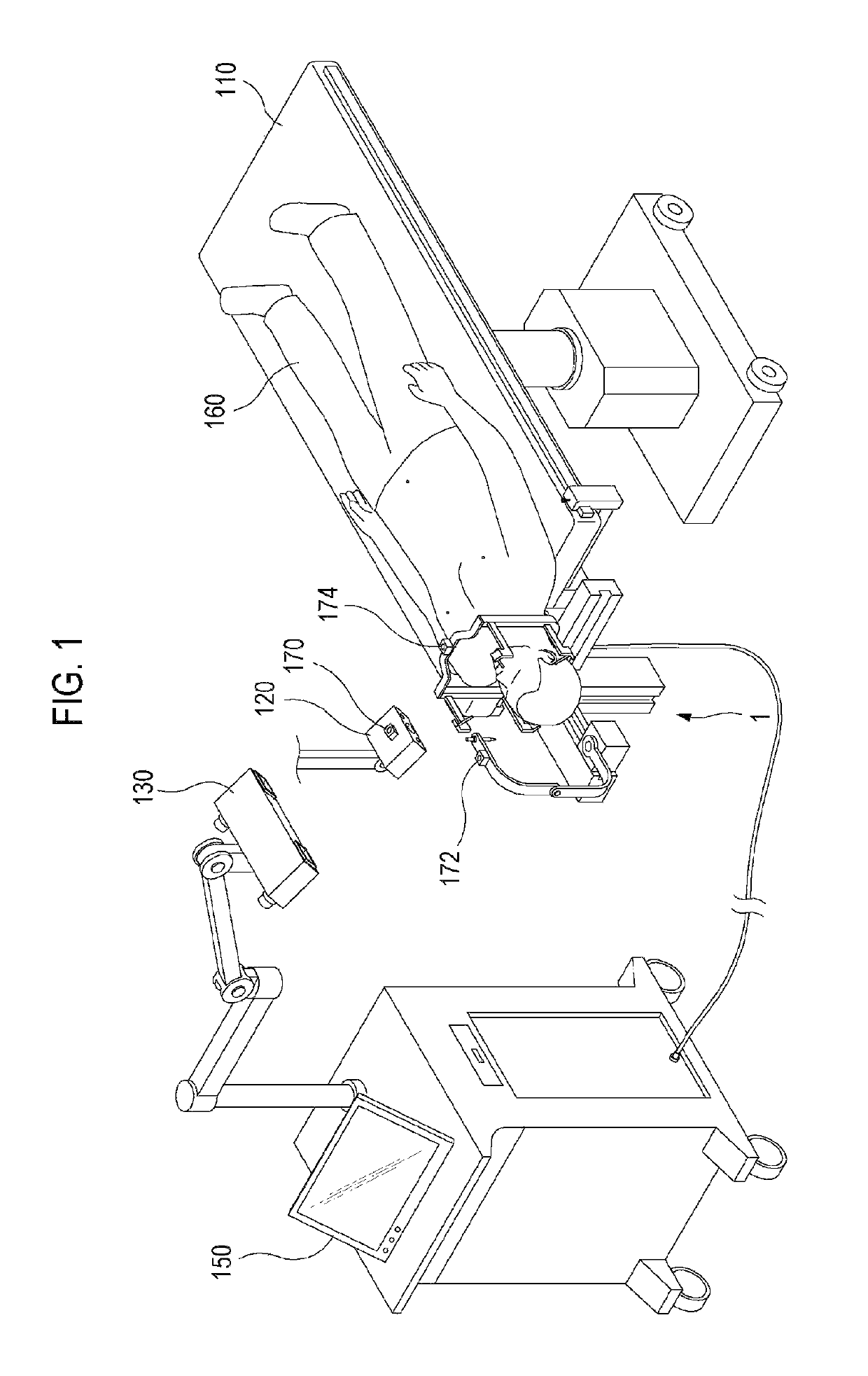
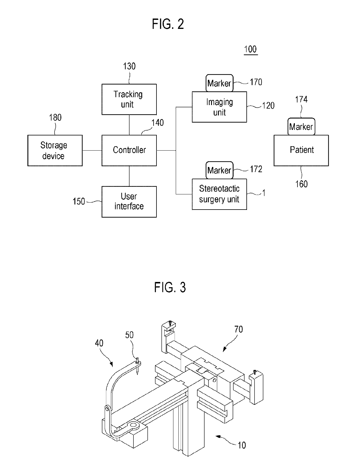
The present invention provides a surgical robot for stereotactic surgery that improves the accuracy of surgery and makes it easier for the patient to adopt a surgical posture. The invention also provides a method for controlling the robot that reduces control errors and makes it easy to correct errors that occur. The robot can be controlled based on the position of the surgical target and the position of the surgical instrument, making it simpler to control and reducing the complexity of the operation. The robot can be placed close to the affected portion of the patient, improving surgical accuracy and patient convenience. The surgical robot system includes a user interface that simplifies the control of the robot for the surgeon. Even if the patient moves during surgery, the system can quickly reset the coordinate conversion relationship for controlling the robot.

Problems solved by technology

However, in the case of using such a manual stereotactic surgery instrument, since the user should read gradations on the Leksell Frame with the naked eye to then determine and move the position of the surgery instrument, it tends to cause an error between the position of the affected portion and the surgery instrument.
That is, when an error occurs in the operation by using one axis of the robot arm, the error is added to another error that occurs in the operation by using another axis so that the errors caused by all axes are accumulated to then affect the surgical accuracy.
In this case, when an operational error occurs at the driving end that is installed on the base, the error is added to other operational errors of a plurality of robot arms that are connected to the base so that the error is further amplified as it goes to the end of the robot arm.
However, if the distance between the base of the robot arm and the affected portion is shortened, the inertia of the robot arm becomes small.
Therefore, an error tends to occur, and thus, it is difficult to make precise control of the robot arm.
In addition, in the case where the robot arm fixed to the base is disposed around the affected portion, there may be a risk that the user may collide with the robot arm when the user moves around the affected portion so that the movement of the user may be disrupted.
In the case of brain surgery or nerve surgery, if the entry position of a surgical instrument is not properly set, the surgical instrument may come into contact with critical portions of the brain or nerves prior to approaching a surgical target in order to thereby put the patient in unnecessary danger.
Therefore, if an error occurs between the actual position of the surgical instrument and the position of the surgical instrument, which is recognized by the stereotactic surgery robot system, the control of the surgical instrument for correcting the error may be complicated.

Method used


Image

  • Surgical robot system for stereotactic surgery and method for controlling stereotactic surgery robot
  • Surgical robot system for stereotactic surgery and method for controlling stereotactic surgery robot
  • Surgical robot system for stereotactic surgery and method for controlling stereotactic surgery robot

Examples


Embodiment Construction

[0051]Embodiments of the present disclosure, which will be described below, are only examples that are illustrated for the purpose of explaining the present disclosure. The embodiments of the present disclosure may be conducted in various manners, and the present disclosure is not construed to be limited to the embodiments described below or to the detailed description of the embodiments.

[0052]The term “unit” that is used in the present embodiments refers to a software element and a hardware element, such as FPGA (field-programmable gate array) or ASIC (application specific integrated circuit). However, the “unit” is not limited to hardware and software. The “unit” may be configured to be in a storage medium that can be addressed, and may be configured to reproduce one or more processors. Accordingly, as an example, the “unit” includes elements, such as software elements, object-oriented software elements, class elements, or task elements, processors, functions, attributes, procedur...


PUM


Abstract

A surgical robot system for stereotactic surgery, according to the present disclosure, may include: a stereotactic surgery unit to move and rotate a surgical instrument; a controller to receive the first imaging data that represents a three-dimensional image of a surgical portion that includes a surgical target; one or more markers to be attached to, or disposed near, the surgical portion; an imaging unit to create the second imaging data that represents a three-dimensional external image of the surgical portion; and a tracking unit to track the positions and postures of the imaging unit and the markers. The controller may create the coordinate conversion relationships for converting a coordinate from the first coordinate system of the first imaging data into the fourth coordinate system of the stereotactic surgery unit and control the stereotactic surgery unit by using the coordinate conversion relationships above.

Description

CROSS-REFERENCE TO RELATED APPLICATIONS[0001]The present application claims priority from Korean Patent Application No. 10-2016-0103717 filed on Aug. 16, 2016, the entire subject matter of which is incorporated herein by reference.TECHNICAL FIELD[0002]The present disclosure relates to a surgical robot system for stereotactic surgery, and further relates to a method for controlling a stereotactic surgery robot.[0003]The present disclosure is derived from research conducted as a part of the Robot Industry Fusion Core Technology Development Project of the Ministry of Trade, Industry and Energy. [Project No. 10062800, Project Title: Development of Practical Technology of Medical Imaging based Brain Surgery Robot System through Clinical Trial]BACKGROUND ART[0004]Various stereotactic surgery instruments have been known. For example, Leksell Frame is used as a manual stereotactic surgery instrument for brain surgery. Leksell Frame has a structure in which a user is able to manually move th...

Claims


Application Information

Patent Timeline
Patent Type & Authority Patents(United States)
IPC IPC(8): A61B90/10A61B90/00A61B34/30B25J9/16A61B34/20A61B34/00A61B34/32A61B90/11A61B90/14
CPCA61B90/14B25J9/1664A61B90/39A61B34/32A61B90/10A61B34/25A61B34/20A61B34/30B25J9/1602A61B90/11B25J9/1697A61B2034/2055A61B2034/2072G05B2219/40298A61B2090/364A61B2090/3983A61B2034/254A61B2090/103Y10S901/30A61B2090/373Y10S901/47A61B2034/2065A61B34/70A61B90/361A61B2090/363A61B5/7475G06T11/60G06T2219/2004G06T2219/2016G06T3/06
Inventor SEONG, EUN HYOUNGKWON, YOUNG SIKCHUNG, JAE HEON
Owner KOHYOUNG TECH
Learn More